
Installation Manual


Appendix B B–B-1
Appendix B Electrical Schematic Diagrams
Overview
This appendix contains electrical schematic diagrams that will aid in troubleshooting the dispensing
system. The schematic diagrams included in this appendix are described in Table B-1.
Safety First
Use of engineering drawings to disassemble, service, and reassemble the dispensing system promotes
good safety practices only when used in conjunction with the instructions specified in the Safety section
and other sections of this manual.
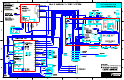
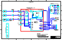
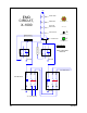
Electrical Schematic Diagrams
TIP It may be easier to trace circuit paths by viewing or printing the colored diagrams located
on the CD version of this manual.
Table B-1 Electrical Schematics
Drawing Number Title
None EMO Circuit, X-1000
SC60-078500 PWA, Home/Limit Switch
SC60-120000 Schematic, Main Interface PWA
SC60-121100 Schematic, XY Servo Interface PWA
SC60-121200 Schematic, Servo Amp PWA
SC60-122001 Schematic, Z Servo Interface PWA
SC60-124001 Schematic, Power Manager PWA
SC60-126500 Schematic, XY Conveyor Interconnect PWA
194030SC Schematic, 555 Conveyor Controller