
Installation Manual


Appendix A A–A-1
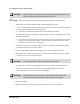
Appendix A Block Diagrams
Overview
This appendix contains electrical and pneumatic block diagrams that describe the major electrical and
pneumatic systems. These diagrams may help in understanding dispensing system operation and aid in
troubleshooting. The diagrams included in this appendix are described in Table A-1 and Table A-2.
Safety First
Use of engineering drawings to disassemble, service, and reassemble the dispensing system promotes
good safety practices only when used in conjunction with the instructions specified in the Safety section
and other sections of this manual.
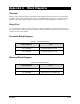
Pneumatic Block Diagrams
Table A-1 Pneumatic Diagrams
Drawing Number Title
62-1710-00PD Pneumatic Diagram, X-1010
62-1720-00PD Pneumatic Diagram, X-1020
Electrical Block Diagrams
Table A-2 Electrical Diagrams
Drawing Number Title
62-1710-00BD Block Diagram, C-1010 Machine
62-1720-00BD Block Diagram, C-1020 Machine