
Installation Manual


Parts Replacement 10-33
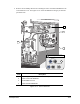
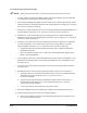
11. Connect the following, if present, on the Valve 1 Electrical/Pneumatic Bulkhead (see
Figure 10-13):
a. Clear pneumatic hose to the pneumatic fitting labeled
FLUID PRESSURE.
b. Black and blue Valve 1 pneumatic hoses to the matching color pneumatic fittings
labeled
VALVE 1.
c. Valve 1 power cable to the connector labeled
VALVE NUMBER 1.
d. Height Sensor power cable to the connector labeled
HEIGHT SENSOR.
e. Low Fluid Sensor power cable to the connector labeled
LOW FLUID SENSOR.
f. Needle Heater power cable to the connector labeled
NEEDLE HEATER.
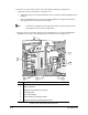
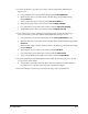
12. If the dispensing system has a Dual-Action Dispensing Head, connect the following, if
present, on the Valve 2 Electrical and Pneumatic Bulkheads (see Figure 10-14):
a. Clear pneumatic hose from the Fluid Syringe to the
FLUID PRESSURE #2 fitting.
b. Black and blue Valve 2 pneumatic hoses to the matching color pneumatic fittings labeled
VALVE #2.
c. Black and blue Toggle Cylinder pneumatic hoses to the matching color pneumatic fittings
labeled
TOGGLE.
d. Dispensing Valve power cable to the connector labeled
VALVE #2.
e. Low Fluid Sensor power cable to the connector labeled
LOW FLUID #2.
f. Valve 2 Needle Heater power cable to the connector labeled
N. HEATER #2.
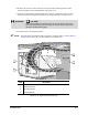
13. Perform a Preliminary Dispensing Head Clearance Check as specified in the Power-up and
Testing section of this manual.
> The pneumatic lines and/or electrical cables should not impede the Dispensing Head
movement or be in a position where they may be pinched or snagged.
14. Perform a Post-Service Start-up as specified in the Safety section of this manual.