
Installation Manual


10-32 Parts Replacement
To install the Dispensing Head Assembly:
? NOTE Apply removable thread locker to all threaded fasteners unless otherwise noted.
1. Carefully lift the new Dispensing Head assembly into position aligning the holes behind the
Z-Carriage Plate with the holes in the X-Pulley Bracket.
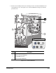
2. While holding the Dispensing Head in position, install the two 4-mm socket head cap screws
attaching the front of the Dispensing Head to the X-Pulley Bracket. See Figure 10-15. Torque
the screws to 50 in-lbs (0.576 kg-m).
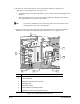
3. Install the two 4-mm socket head cap screws attaching the back of the Dispensing Head to the
X-Pulley Bracket. See Figure 10-16. Torque the screws to 50 in-lbs (0.576 kg-m).
4. Install the two 3-mm socket head cap screws attaching the Valve 1 Electrical/Pneumatic
Bulkhead to the bottom of the Dispense Head Controller Cover. See Figure 10-15. Torque the
screws to 25 in-lbs (0.288 kg-m).
5. Install the 3-mm socket head cap screws attaching the following components, as applicable,
to the Z-Carriage Plate. Use the same holes on the new Z-Carriage Plate as on the old
Dispensing Head. See Figure 10-15. Torque the screws to 25 in-lbs (0.288 kg-m).
• Single Dispensing Valve Mounting Bracket (includes Valve 1 Bracket and attached
Height Sensor Bracket)
• Dual Valve Bracket (includes Valve 1 and Valve 2 Mounting Brackets, Height Sensor
Bracket, and Toggle Bracket)
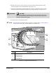
6. Align the holes on the Valve 2 Pneumatic Bulkhead with those on the Counterbalance Cover.
Reinstall the two Phillips head screws attaching the Bulkhead to the Counterbalance Cover.
See Figure 10-14.
7. Connect all of the cables to their appropriate connections on the Dispense Head Controller.
See Figure 10-13.
8. Reinstall the Camera with its attached mounting brackets as follows (see Figure 10-13):
a. Align the holes on the Vertical Camera Bracket with the holes on the X-Pulley Bracket.
Install the two 3-mm socket head cap screws. Torque the screws to
25 in-lbs (0.288 kg-m).
b. Align the holes on the Horizontal Camera Bracket with the holes on the bottom of
the Dispensing Head. Install the two 3-mm socket head cap screws. Torque the
screws to 25 in-lbs (0.288 kg-m).
c. Connect the Camera Coaxial Cable to the top of the Camera.
9. Reinstall the Height Sensor on the Height Sensor Bracket with the Phillips head screws.
10. Install the Dispensing Valve(s) on the new Dispensing Head.
> Refer to the installation procedure in the applicable Dispensing Valve Installation and
Operations Manual if necessary.