
Installation Manual


10-30 Parts Replacement
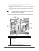
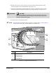
10. Remove the 3-mm socket head cap screws attaching the following components (as
applicable) to the Z-Carriage Plate. See Figure 10-15.
• Single Dispensing Valve Mounting Bracket (Valve 1 Bracket and attached Height Sensor
Bracket)
• Dual Valve Bracket (Valve 1 and Valve 2 Mounting Brackets, Height Sensor Bracket,
and Toggle Bracket are mounted on this bracket)
TIP To facilitate reinstallation of the components, make note of the location of the
mounting holes used on the Z-Carriage Plate.
11. Remove the two 3-mm socket head cap screws attaching the Valve 1 Electrical/Pneumatic
Bulkhead to the bottom of the Dispense Head Controller Cover. See Figure 10-15.
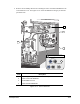
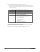
Item Description
1 X-Pulley Bracket
2 Valve 1 Bulkhead
3 Bulkhead-to-Controller Cover Screws
4 Z-Carriage Plate
5 Dual Valve Bracket
6 Valve Bracket-to-Z-Carriage Screws
7 Dispensing Head to X-Pulley Bracket Screws
Figure 10-15 Dispensing Head Front View
2
3
7
6
1
4 5