
Installation Manual


Parts Replacement 10-29
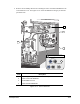
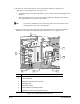
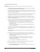
9. Remove the two Phillips head screws attaching the Valve 2 Pneumatic Bulkhead to the
Counterbalance Cover. See Figure 10-14. Allow the Bulkhead to hang by its attached
pneumatic lines.
Item Description
1 Dispensing Valve (DV-7000 shown as Valve 2)
2 Valve 2 Pneumatic Bulkhead
3 Counterbalance Cover
4 Valve 2 Electrical Bulkhead
Figure 10-14 Valve 2 Bulkheads
1
4
2
3
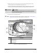
TOGGLE
VALVE #2
FLUID PRESSURE
#2
Top View