
Installation Manual


10-28 Parts Replacement
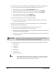
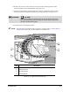
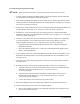
4. If the dispensing system has a Dual-Action Dispensing Head, disconnect the following, if
present, on the Valve 2 Electrical and Pneumatic Bulkheads (see Figure 10-14):
a. Clear pneumatic hose from the
FLUID PRESSURE #2 fitting.
b. Black and blue pneumatic hoses from the pneumatic fittings labeled
VALVE #2.
c. Black and blue pneumatic hoses from the pneumatic fittings labeled
TOGGLE.
d. Power cable from the connector labeled
VALVE #2.
e. Power cable from the connector labeled
LOW FLUID #2.
5. Remove the Dispensing Valve(s) from the Dispensing Head.
> Refer to the removal procedure in the applicable Dispensing Valve Installation and
Operations Manual if necessary.
6. Remove the three Phillips head screws attaching the Height Sensor to the Height Sensor
Bracket and remove the Height Sensor.
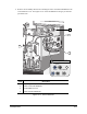
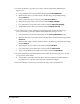
7. Remove the Camera and its support brackets as follows (see Figure 10-13):
a. Disconnect the coaxial cable from the top of the Camera.
b. Remove the two 3-mm socket head cap screws attaching the Horizontal Camera Bracket
to the bottom of the Dispensing Head.
c. Remove the two 3-mm socket head cap screws attaching the Vertical Camera Bracket to
the X-Pulley Bracket.
CAUTION! Make sure to hold onto the Camera when you remove the bottom screws to
prevent the Camera from falling and possibly being damaged.
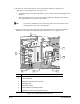
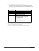
8. Disconnect all cables connected to the Dispense Head Controller including the following:
• Height Sensor
• Light Source
• CAN Bus-In
• CPC Header
• Valve Control
• Pneumatic Solenoid
TIP When disconnecting cables, take note of where they are connected. Cables are
usually labeled and are referenced on the schematics in Appendix B of this
manual. Label the cables and connections if necessary.