
Installation Manual


10-26 Parts Replacement
Replacing the Dispensing Head
Use the following procedure to remove and replace the Dispensing Head Assembly if fault isolation
procedures in the Troubleshooting section of this manual have confirmed that it is faulty.
CAUTION! This procedure should only be performed by a trained service technician.
Tools and Materials Needed
• 3-mm Hex Key • Phillips Head Screwdriver
• 4-mm Hex Key • Torque Wrench
To remove the Dispensing Head Assembly:
? NOTE All components and fasteners removed during this procedure should be retained in an
orderly manner and in a safe location for reinstallation or shipment back to Asymtek.
1. Perform a Service Shutdown as specified in the Safety section of this manual.
WARNING! Allow all Heaters to become cool or use thermal PPE before proceeding with this
procedure. Failure to do so may cause serious burn injury to occur.
2. Open the Hatch.
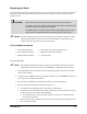
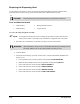
3. Disconnect the following, if present, from the Valve 1 Electrical/Pneumatic Bulkhead (see
Figure 10-13):
a. Clear pneumatic hose from the pneumatic fitting labeled
FLUID PRESSURE.
b. Black and blue pneumatic hoses from the pneumatic fittings labeled
VALVE 1.
c. Power cable from the connector labeled
VALVE NUMBER 1.
d. Power cable from the connector labeled
HEIGHT SENSOR.
e. Power cable from the connector labeled
NEEDLE HEATER.
f. Power cable from the connector labeled
LOW FLUID SENSOR.