
Installation Manual


Parts Replacement 10-25
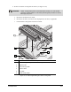
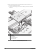
c. Place the Breeze Shield into the Weigh Station hole in the DCM so it rests on the Top
Plate of the Balance Module.
d. Carefully install the Scale Pedestal by placing it straight down inside the Breeze Shield.
CAUTION! Avoid putting pressure on the Scale Pedestal or damage to the sensitive
weighing mechanism will occur.
e. Install a clean plastic cup on the Scale Pedestal inside the Breeze Shield.
f. Install the Weigh Station Cover.
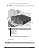
7. Reinstall the Dispensing Area Front Cover as follows (see Figure 10-8):
a. Position the Cover on the brackets at the front of the dispensing chamber such that the
fasteners align with the holes.
b. Turn each of the six Phillips head fasteners 1/4-turn to secure the Cover to the
mounting brackets.
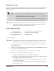
8. Install the new Scale Control Module in the Rear Cabinet as follows (see Figure 10-7):
a. Place the Scale Control Module on the Cabinet floor and align the holes.
b. Install the two 4-mm socket head cap screws and washers. Torque the screws to 25 in-lbs
(0.288 kg-m).
c. Connect the Scale Communication Cable, Scale Power Cable, and the Scale Interconnect
Cable to the Scale Control Module.
To prepare the new Scale for operation:
1. Level the Dispensing Calibration Module in relation to a sample workpiece in accordance
with “Dispensing Calibration Module Leveling and Height Adjustment” in the Calibration
and Adjustment section of this manual.
? NOTE Leveling the Scale requires the dispensing system to be level. Refer to “Leveling
the Dispensing System” in the Power-up and Testing section of this manual
.
2. Perform Valve Offset Routine in accordance with the FmNT User Guide.
3. Calibrate the Scale in accordance with “Scale Leveling and Calibration” in the Calibration
and Adjustment section of this manual.
? NOTE The FmNT software Setup and Configuring of the Scale is done at the Asymtek
factory. If the Scale is inadvertently disabled, contact Asymtek Technical
Support on how to proceed.