
Installation Manual


10-24 Parts Replacement
To install the Scale:
? NOTE Apply removable thread locker to all threaded fasteners unless otherwise noted.
1. Open the package containing the new Scale (P/N 392364) and verify that the serial numbers
on the Scale Control Module and the Balance Module are identical. Enter the serial numbers
in the maintenance/service records.
? NOTE Contact Asymtek Technical Support if serial numbers are not identical.
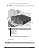
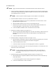
2. Install the Balance Module on the Conveyor Base Plate as follows:
a. Place the Balance Module onto the Conveyor Base Plate such that the cable is on the
right-hand side (see Figure 10-12).
b. Slide the module under the front Conveyor rail and align the holes.
c. Install the four 4-mm socket head cap screws that attach the Balance Module to the
Conveyor Base Plate. Torque the screws to 25 in-lbs (0.288 kg-m).
d. Connect the Balance Module Cable to the Scale Interconnect Cable.
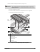
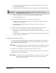
3. Install the Lift Table as follows (see Figure 10-11):
a. Slide the Top Plate Guide Rod straight down into the Linear Bearing. Make sure the Lift
Module Guide Rod slides into the hole in the Pillow Block on the underside of the
Lift Table.
b. Connect the blue Pneumatics Hose.
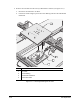
4. Install the Heater Tooling Plate as follows (see Figure 10-10):
a. Place the Heater Tooling Plate on the Lift Table such that the alignment pins on the Lift
Table go into the holes on the bottom of the Heater Tooling Plate.
b. Connect the Heater Power Cable.
c. Connect the white Vacuum Hose or blue Impingement Air Hose, as applicable.
5. Level the Scale in accordance with “Scale Leveling and Calibration” in the Calibration and
Adjustment section of this manual.
? NOTE Leveling the Scale requires the dispensing system to be leveled. Refer to
“Leveling the Dispensing System” in the Power-up and Testing section of
this manual
.
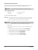
6. Install the Dispensing Calibration Module (DCM) as follows (see Figure 10-9):
a. Place the DCM on the Adjustment Bracket and install the three 4-mm socket head cap
screws and washers.
> Do not fully tighten the screws until leveling has been completed.
b. Connect the Needle Sensor Cable to the DCM.