
Installation Manual


Troubleshooting 8-143
Scale Power Verification
1. Open Lower Front Cabinet Door and open the Computer Door.
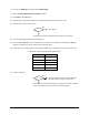
2. Locate LED
D2 (+12 VDC) on the Main Interface PWA.
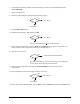
3. Is LED
D2 illuminated?
Go to Step 4
Go to Step 7
4. Exit FmNT, shut down Windows NT, press the black OFF (0) button on the Operator’s Console,
switch Main Circuit Breaker to
OFF (0) position, and disconnect Power Cable from the facility outlet.
5. Locate and inspect Fuse F2 on the Main Interface PWA.
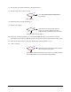
6. Is the fuse open?
Go to Step 7
Replace fuse (P/N 194018)
7. Disconnect the Scale Power Cable (P/N 06-4580-00) from rear of Scale Control Module.
8. Connect the Power Cable to facility outlet, switch Main Circuit Breaker to
ON (I), press the green ON
(I) button on the Operator’s Console, and enter FmNT.
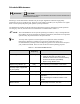
9. Measure VDC at Pin 1 and Pin 3 of P2 on the cable.
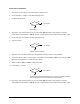
10. Is the reading +12 VDC?
Go to Step 11
Scale (P/N 62-1614-00) has failed. See
Parts Replacement section. (Balance
and Control Modules must be a matched set by serial number.)
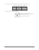
11. Exit FmNT, shut down Windows NT, press the black OFF (0) button on the Operator’s Console,
switch Main Circuit Breaker to
OFF (0) position, and disconnect Power Cable from the facility outlet.
No
Yes
No
Yes
No
Yes