
Installation Manual


8-138 Troubleshooting
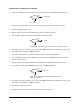
12. Locate the backside of J24 on the Main Interface PWA labeled NEEDLE SENSORS.
13. Measure VDC between Pin 4 and Pin 5 on J24.
14. Is the reading 24 VDC?
Main Interface PWA (P/N 60-1200-00) has failed.
See
Parts Replacement section.
Go to Step 15
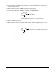
15. Locate backside of J24 on the Main Interface PWA labeled NEEDLE SENSORS.
16. Measure VDC between Pin 3 and Pin 2 on J24 while toggling the Needle Sensor.
17. Does the signal change from 24 VDC to 0 VDC?
Go to Step 18
Main Interface PWA (P/N 60-1200-00) has failed. See Parts
Replacement
section.
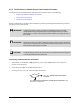
18. Check the Needle Sensor Cable (P/N 06-4599-00) for continuity (Pinout is 1 to 1).
19. Does the cable have continuity?
Needle Sensor Cable (P/N 06-4599-00) has failed.
See
Parts Replacement section.
Needle Sensor (P/N 62-1617-00) has failed. See
Parts Replacement section.
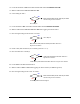
20. Locate U22 on the Main Interface PWA.
21. Measure VDC at Pin 1 on U22 while toggling the Needle Sensor (use TP1 for ground).
22. Does the signal change from 5 VDC to 0 VDC?
Main Interface PWA (P/N 60-1200-00) has failed.
See
Parts Replacement section.
Contact Asymtek Technical Support
No
Yes
No
Yes
No
Yes
No
Yes