
Installation Manual


Troubleshooting 8-131
Height Sensor CAN Interface Verification
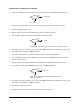
1. Is the CAN terminator connector connected to the Bus-out port on the Dispense Head Controller?
Go to Step 2
Go to Step 3
2. Connect the CAN terminator connector to the Bus-out port on the Dispense Head Controller.
3. Remove the Height Sensor Cover.
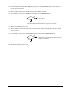
4. Measure VDC at locations 3 and 8 on the PCB where the cable is connected.
5. Is the reading 5 VDC in the Arm state and 0 VDC in the Disarm State?
Go to 6
Height Sensor (P/N 195428) has failed. See Parts Replacement section.
6. Exit FmNT, Shut down Windows NT, press the black OFF (0) button on the Operator’s Console, and
switch Main Circuit Breaker to
OFF (0) position.
7. Disconnect the Height Sensor Cable (P/N 06-4590-00) from the Dispensing Head.
8. Switch the Main Circuit Breaker to
ON (I) position, press the green ON (I) button on the Operator’s
Console, and enter FmNT.
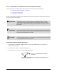
9. Measure VDC between Pin 7 and Pin 2 on the Dispense Head Height Sensor Cable receptacle.
10. Is the reading 5 VDC in the Armed state and 0 VDC in the Disarmed state?
Go to 11
Height Sensor Cable (P/N 06-4590-00) has failed. See Parts
Replacement
section.
11. Exit FmNT, Shut down Windows NT, press the black OFF (0) button on the Operator’s Console, and
switch Main Circuit Breaker to
OFF (0) position.
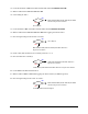
12. Reinstall the Height Sensor Cover.
13. Disconnect the Cable (P/N 195296) from the Dispense Head Controller.
No
Yes
No
Yes
No
Yes