
Installation Manual


Troubleshooting 8-101
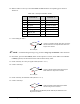
30. Measure VDC on Conveyor Controller J3 Pin 1 or Pin 2 and the corresponding pin as shown in
Table 8-30.
Table 8-30 Conveyor Controller J3 Pins
Pin Conveyor
Controller J3
Pin Conveyor
Controller J3
1 +24 VDC 8 Stop Pin, right
2 +24 VDC 9 Vacuum on left
3 Lift up left 10 Vacuum on center
4 Left up center 11 Vacuum on right
5 Lift up right 12 Purge Cup air on
6 Stop Pin, left ~
7 Stop Pin, center 25
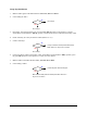
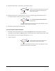
31. Is the reading 24 VDC?
Conveyor Controller (P/N 62-1677-00 for X-1020 or
P/N 62-1676-00 for X-1010) has failed. See
Parts
Replacement
section.
Go to Step 32
? NOTE If troubleshooting the Purge Cup, proceed to Purge Cup Verification in this subsection.
32. Exit FmNT, press the black
OFF (0) button on the Operator’s Console, switch Main Circuit Breaker
to
OFF (0) position, and disconnect Power Cable from the facility outlet.
33. Check continuity of Conveyor Signals Cable (Pinout is 1 to 1).
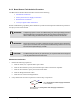
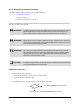
34. Is there continuity?
Conveyor Signals Cable (P/N 06-4610-00) has
failed. See
Parts Replacement section.
Go to Step 35
35. Check continuity of Solenoids Cable (Pinout is 1 to 1).
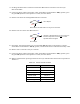
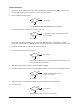
36. Is there continuity?
Solenoids Cable (P/N 06-4620-00) has failed.
See
Parts Replacement section.
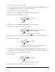
Conveyor Interconnect Module (P/N 60-1265-00) has failed. See
Parts
Replacement
section.
No
Yes
No
Yes
No
Yes