
Installation Manual


8-76 Troubleshooting
13. Switch the Main Circuit Breaker to the OFF (0) position.
14. Disconnect the Z-Head Interconnect Cable (P/N 06-4550-00) from the rear of the Dispensing Head at
the Z Servo Interface PWA connection J2 connector.
15. Switch the Main Circuit Breaker to the
ON (I) position.
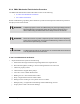
WARNING! CAUTION!
Use caution when reaching your hand into the dispensing chamber while system
is under power. Failure to take appropriate precautions could result in serious
injury or property damage.
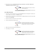
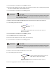
16. Measure VDC between Pin 1 and Pin 23 of the Z-head Interconnect Cable (P/N 06-4550-00).
17. Is the reading greater than 4 VDC?
Go to 18
Z-Head Servo Interface PWA (P/N 60-120-01) has failed. See Parts
Replacement
section.
18. Switch the Main Circuit Breaker to the OFF (0) position.
19. Locate J31 on the XY Servo Interface PWA.
20. Disconnect the Z-Head Interconnect Cable (P/N 06-4550-00).
21. Switch the Main Circuit Breaker to the
ON (I) position.
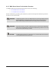
WARNING! CAUTION!
Use caution when reaching your hand into the dispensing chamber while system
is under power. Failure to take appropriate precautions could result in injury or
property damage.
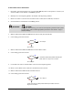
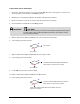
22. Measure VDC between Pin 1 and Pin 23 at connector J31.
23. Is the reading greater than 4 VDC?
XY Servo Interface Board (P/N 60-1211-00) has
failed. See
Parts Replacement section.
Z-Head Interconnect Cable (P/N 06-4550-00) has failed. See
Parts
Replacement
section.
24. Place an opaque plastic card into the X-axis Home Sensor slot.
No
Yes
No
Yes