
Installation Manual


8-60 Troubleshooting
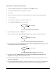
15. At the Y-axis Servo Motor, the Rotary Encoder Cable, the black wire on Rotary Encoder Cable
should be orientated to Pin 1 labeled GND with the copper lead facing you.
16. Carefully remove the Servo Motor Connector (leads are fragile) and check for damage.
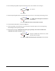
17. Are any of the Servo Motor leads damaged?
Go to Step 18
Servo Motor (P/N 62-1650-01) has failed. See
Parts Replacement section.
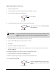
18. Check continuity of Rotary Encoder Cable (P/N 06-4535-00).
19. Does the Cable have continuity?
Rotary Encoder Cable (P/N 06-4535-00) has failed.
See
Parts Replacement section.
Go to Step 20
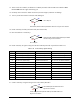
20. Check continuity of signal routing from the Y-axis Rotary Encoder as specified in Table 8-20.
Table 8-20 Y-axis Rotary Signal Routing
Signal
From (PWA)
Via
To (PWA)
B Pin 3 at J3 (Servo Amp) Y-axis Servo amp PWA Pin 14 at J5 (Servo Amp)
A Pin 5 at J3 (Servo Amp) Y-axis Servo amp PWA Pin 13 at J5 (Servo Amp)
B Pin 14 at J5 (Servo Amp) Cable P/N 06-0403-00 Pin 14 at J9 (XY Servo Interface)
A Pin 13 at J5 (Servo Amp) Cable P/N 06-0403-00 Pin 13 at J9 (XY Servo Interface)
B Pin 14 at J9 (XY Servo Interface) XY Servo Interface PWA Pin 23 at J19 (XY Servo Interface)
A Pin 13 at J9 (XY Servo Interface) XY Servo Interface PWA Pin 22 at J19 (XY Servo Interface)
B Pin 23 at J19 (XY Servo Interface) Cable P/N 06-4525-00 Pin 23 at J29 (Main Interface)
A Pin 22 at J19 (XY Servo Interface) Cable P/N 06-4525-00 Pin 22 at J29 (Main Interface)
B Pin 23 at J29 (Main Interface) Main Interface PWA Pin 13 at J9 (Main Interface)
A Pin 22 at J29 (Main Interface) Main Interface PWA Pin 14 at J9 (Main Interface)
B Pin 13 at J9 (Main Interface) Cable P/N 06-4523-00 Pin 13 at J8 PMAC Controller
A Pin 14 at J9 (Main Interface) Cable P/N 06-4523-00 Pin 14 at J8 PMAC Controller
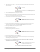
21. Is there continuity of signal routing for the Y-axis Rotary Encoder?
The isolated part has failed. See Parts
Replacement
section.
Y-axis Rotary Encoder (P/N 62-1650-01) has failed. See
Parts
Replacement
section.
No
Yes
No
Yes
No
Yes