
Installation Manual


8-48 Troubleshooting
Power-up Reset Check
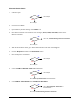
1. Locate the XY Servo Interface PWA power LEDs.
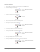
2. Is the green +SERVO LED illuminated?
Go to Servo Power Verification in this subsection.
Go to Step 3
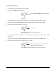
3. Locate the J4 power connection at on the X and Y Servo Amplifier PWAs on the Servo Shelf.
4. Measure VDC between Pin 1 and Pin 2 of Power Cable (P/N 06-4534-00) connected to J4.
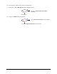
5. Is the reading at both Amplifiers 67.5 ±2 VDC?
Go to Step 6
Servo Amplifier (P/N 60-1212-00) has failed. See Parts
Replacement
section.
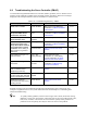
6. On the XY Servo Interface PWA, locate the Servo Amplifier power connections J8 for Y-axis and J6
for X-axis.
7. Measure the VDC between Pin 1 and Pin 2 of Power Cable (P/N 06-4534-00) at J8 and J6.
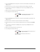
8. Do both connector locations have readings of 67.5 ±2 VDC?
Servo Interface PWA (P/N 60-1211-00) has failed.
See
Parts Replacement section.
Cable (P/N 06-4534-00) has failed. See
Parts Replacement section.
No
Yes
No
Yes
No
Yes