
Installation Manual


Troubleshooting 8-43
Servo Power Verification
1. On the XY Servo Interface PWA, locate the J3 connector.
2. Confirm there are two blue wires attached to the J3 connector labeled SERVO DC POWER
ENTRY (the positions of these wires are labeled +SERVO).
3. Measure the VDC at the connector where each of the two blue wires come into J3 (Use TP1 labeled
SERVO_RETURN on the XY Servo Interface PWA for ground).
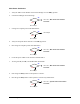
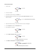
4. Is the reading 67.5 ±2 VDC for each blue wire?
Go to Step 5
XY Servo Interface PWA (P/N 60-1211-00) has failed. See Parts
Replacement
section.
5. Press the black OFF (0) button on the Operator’s Console and switch the Main Circuit Breaker to the
OFF (0) position.
6. Locate the Servo Transformer on the Servo Shelf.
7. Disconnect the Servo AC Power Cord (P/N 56-0304-00) from the Servo Transformer AC POWER
inlet.
8. Check continuity of the two 8 Amp fuses in the Fuse Tray on the Servo Transformer AC POWER
inlet. NOTE: The outward fuse is a spare and the inward fuse is connected to the circuit.
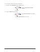
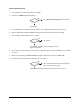
9. Is there continuity on both fuses?
Replace fuse (P/N 55-5392). See Parts
Replacement
section. Then go to Step 10.
Go to Step 14
10. Reconnect the Servo AC Power Cord (P/N 56-0304-00) to the Servo Transformer AC POWER inlet.
11. Switch the Main Circuit Breaker to the
ON (I) position and press the green ON (I) button on the
Operator’s Console.
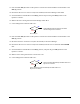
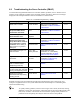
12. Is the green +SERVO LED illuminated?
Go to Step 13
Stop here. The fuse is the root cause of Servo Power fault. If the
Servo Amplifier fault continues, go to Servo Amplifier Verification
in this subsection.
No
Yes
No
Yes
No
Yes