
Installation Manual


Troubleshooting 8-37
Hatch Open Signal Verification
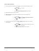
1. Verify the Servo Interconnect A Cable (P/N 06-4525-00) is connected to XY Servo Interface PWA
J19 and the Main Interface PWA J29.
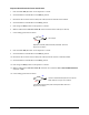
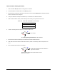
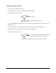
2. Locate chips U15 and U14 on the Main Interface PWA on the Computer Door.
3. With the Front Hatch closed, measure the VDC at Pin 10 of chips U14 and U15 on the Main
Interface PWA. Use TP2 labeled GND for ground.
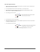
4. Is the reading greater than 4 VDC?
Main Interface PWA (P/N 60-1200-00) has failed.
See
Parts Replacement section.
Go to Step 5
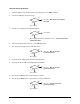
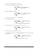
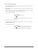
5. Locate chip U5 on XY Servo Interface PWA.
6. With the Front Hatch closed, measure the VDC at Pin 2 of chip U5 on the XY Servo Interface PWA.
Use TP8 labeled GND for ground.
7. Is the reading greater than 4 VDC?
Servo Signal Interconnect Cable A (P/N 06-4525-00)
has failed. See
Parts Replacement section.
Go to Servo Low Power Signal Verification in this subsection.
No
Yes
No
Yes