
Installation Manual


8-36 Troubleshooting
Interlock Switch Cabling Verification
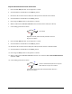
1. Press the black
OFF (0) button on the Operator’s Console.
2. Switch the Main Circuit Breaker to the
OFF (0) position.
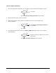
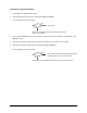
3. Disconnect the Cable (P/N 06-4528-00) from the connector labeled Interlock on the Main Interface
PWA on the left side of Computer.
4. Verify the Interlock Cable (P/N 06-4528-00) is connected to the Interlock Switch.
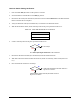
5. With the Front Hatch closed, check continuity between the pins specified in Table 8-16.
Table 8-16 Cable P/N 06-4528-00 Pin Connections
Pin Connections
Pin 1 to Pin 2
Pin 3 to Pin 4
6. Is there continuity between the pins specified in Table 8-16?
Go to Step 7
Go to Hatch Open Signal Verification in this subsection.
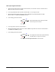
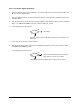
7. Disconnect the Interlock Cable (P/N 06-4528-00) from the Interlock Switch.
8. With both ends of the Interlock Cable disconnected, check for continuity of the Cable (Pinout is 1
to 1).
9. Does the Interlock Cable have continuity?
Cable (P/N 06-4528-00) has failed. See Parts
Replacement
section.
Interlock Switch (P/N 62-1638-00) has failed. See
Parts
Replacement
section.
No
Yes
No
Yes