
Installation Manual


Troubleshooting 8-31
Dispense Head Controller Power Verification
1. Press the black
OFF (0) button on the Operator’s Console.
2. Switch the Main Circuit Breaker to the
OFF (0) position.
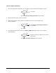
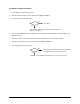
3. Disconnect the 555 Interconnect Cable (P/N 194154) from the left side of the Z-Head.
4. Switch the Main Circuit Breaker to the
ON (I) position.
5. Press the green
ON (I) button on the Operator’s Console.
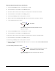
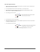
6. Measure VDC between Pin 25 and Pin 10 on the 555 Interconnect Cable (P/N 194154).
7. Is the reading greater than 23 VDC?
Go to Step 8
Dispense Controller (P/N 60-1250-00) has failed. See
Parts
Replacement
section.
8. Press the black OFF (0) button on the Operator’s Console.
9. Switch the Main Circuit Breaker to the
OFF (0) position.
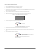
10. Disconnect the 555 Interconnect Cable (P/N 194154) from the XY Servo Interface Board.
11. Switch the Main Circuit Breaker to the
ON (I) position.
12. Press the green
ON (I) button on the Operator’s Console.
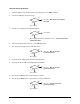
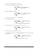
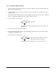
13. Measure VDC between Pin 25 and Pin 10 on the XY Servo Interface Board 555 INTERCONNECT
connector at J24.
14. Is the reading greater than 23 VDC?
XY Servo Interface Board (P/N 60-1211-00) has
failed. See
Parts Replacement section.
The 555 Interconnect Cable (P/N 194154) has failed. See
Parts
Replacement
section.
No
Yes
No
Yes