
Installation Manual


8-30 Troubleshooting
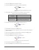
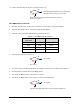
15. Measure VDC between Pin 1 and Pin 2 at the Power Manager +24V DC POWER OUT connector.
16. Is the reading greater than 23 VDC?
Power Manager (P/N 62-1620-01) has failed.
See
Parts Replacement section.
Cable (P/N 06-4510-00) has failed. See
Parts Replacement section.
17. Press the black OFF (0) button on the Operator’s Console.
18. Switch the Main Circuit Breaker to the
OFF (0) position.
19. Disconnect the DC Power Cable (P/N 06-4530-00) from the Main Interface Board XY SERVO DC
POWER connector.
20. Switch the Main Circuit Breaker to the
ON (I) position.
21. Press the green
ON (I) button on the Operator’s Console.
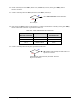
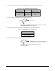
22. Measure VDC between Pin 2 and Pin 3 at the Main Interface Board XY SERVO DC POWER
connector.
23. Is the reading greater than 23 VDC?
Main Interface PWA (P/N 60-1200-00) has failed.
See
Parts Replacement section.
Go to Step 24
24. Press the black OFF (0) button on the Operator’s Console.
25. Switch the Main Circuit Breaker to the
OFF (0) position.
26. Reconnect the DC Power Cable (P/N 06-4530-00) to the Main Interface Board XY SERVO DC
POWER connector.
27. Switch the Main Circuit Breaker to the
ON (I) position.
28. Press the green
ON (I) button on the Operator’s Console.
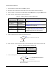
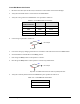
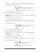
29. Measure VDC between test points TP7 (+24V), and TP6 (Return) on the XY Servo Interface PWA.
30. Is the reading greater than 23 VDC?
Cable (P/N 06-4530-00) has failed. See Parts
Replacement
section.
XY Servo Interface PWA (P/N 60-1211-00) has failed. See
Parts
Replacement
section.
No
Yes
No
Yes
No
Yes