
Installation Manual


Troubleshooting 8-25
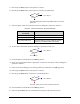
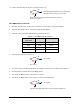
Front EMO Button Verification
1. Reconnect the Cable (P/N 06-4515-00) to the Power Control outlet on the Power Manager.
2. Verify the Front EMO Cable is connected to Front EMO Button.
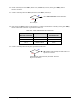
3. Verify the wiring to the Front EMO Button is as specified in Table 8-9.
Table 8-9 Front EMO Cable Connections
Front EMO
Cable Connector
Wire Color Front EMO Button
Pin 1 Black Pin 11
Pin 2 White Pin 12
Pin 3 Red Pin 21
Pin 4 Green Pin 22
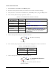
4. Is the wiring as specified in Table 8-9?
Go to Step 5
Go Step 9
5. Correct the wiring by changing connections in accordance with Table 8-9 for the Front EMO Button.
6. Switch the Main Circuit Breaker to the
ON (I) position.
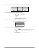
7. Press the green
ON (I) button on the Operator’s Console.
8. Does the green
ON (I) button on the Operator’s Console stay illuminated?
Go to Step 9
Stop here. Front EMO cable is the root cause of system power fault.
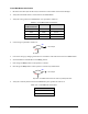
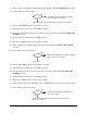
9. Verify the continuity between the Front EMO Button pins specified in Table 8-10.
Table 8-10 Front EMO Pin Connections
Front EMO Button Pins
Pin 11 to Pin 12
Pin 21 to Pin 22
No
Yes
No
Yes