
Installation Manual


8-24 Troubleshooting
Power Cable Verification
1. Switch the Main Circuit Breaker to the
OFF (0) position.
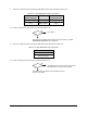
2. Disconnect Cable (P/N 06-4515-00) from the Power Control outlet of the Power Manager.
3. Verify the Cable is connected to front EMO Button, black
OFF (0) button, and green ON (I) button.
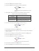
4. Check continuity between the pins specified in Table 8-7.
Table 8-7 Continuity Paths for Cable P/N 06-4515-00
D-Sub Connector
(P/N/ 06-4515-00)
Component
Activation
If No Continuity
Pin 1 to Pin 2 Front EMO
Pin 1 to Pin 3 Front EMO
Go to Front EMO Button Verification in this
subsection.
Pin 4 to Pin 5 OFF (0) Button
Pin 6 to Pin 7 OFF (0) Button
Go to Operator’s Console OFF (0) Button
Verification in this subsection.
Pin 8 to Pin 9 ON (I) Button
Pin 10 to Pin 11 ON (I) Button
Go to Step 20 of “System Power Verification”, in
8.1.3, System Power Fault Isolation Procedure.
The green ON (I) button must be pressed for
continuity check.
5. Is there continuity between the pins specified in Table 8-7?
See Table 8-7 for next Step.
Go to Step 6
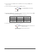
6. Check continuity of pins specified in Table 8-8 at Power Manager Power Control connector J5.
Table 8-8 Continuity Paths for Connector J5
Power Control
Connector J5
Activation
Component
Pin 2 to Pin 4 Rear EMO/Vent
Pin 3 to Pin 6 Rear EMO/Vent
7. Is there continuity between the pins specified in Table 8-8?
Go to Rear EMO Button Verification in
this subsection.
Power Manager (P/N 62-1620-01) has failed. See
Parts
Replacement
section.
No
Yes
No
Yes