
Installation Manual


Troubleshooting 8-23
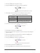
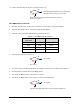
22. Check continuity between Pin 1 (black wire) and Pin 3 (red wire) at the green ON (I) button
harness connector.
23. Is there continuity between Pin 1 (black wire) and Pin 3 (red wire)?
Go to Cable Verification in this subsection.
Go to Step 24
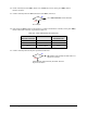
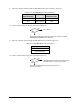
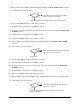
24. Press the green ON (I) button on the Operator’s Console and check the continuity of the green ON (I)
button at the cable connector as specified in Table 8-6.
Table 8-6 Cable P/N 06-4515-00 Connections
Start Button
Harness Connector
Wire Color Cable Connector
P/N 06-4515-00
Pin 1 Black to White Pin 2
Pin 2 Red to Green Pin 4
Pin 3 Brown to Blue Pin 6
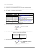
25. Is there continuity between the pins specified in Table 8-6?
ON (I) Switch (P/N 40-2484) has failed. See Parts
Replacement
section.
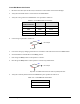
Power Manager (P/N 62-1620-01) has failed. See
Parts
Replacement
section.
No
Yes
No
Yes