
Installation Manual


8-18 Troubleshooting
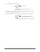
50. Locate J18 on the XY Servo Interface PWA.
51. With the XY Servo DC Power Cable connected to the Main Interface PWA, measure VDC at Pin 1
(connect ground to Pin 4).
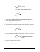
52. Is the reading ≥4 VDC?
XY Servo DC Power Cable (P/N 06-4530-00) has
failed. See
Parts Replacement section.
LED on the XY Servo Interface PWA (P/N 60-1211-00) has failed. See
Parts
Replacement
section.
53. Switch the Main Circuit Breaker to the OFF (0) position.
54. Check continuity of the fuses on the Main Interface PWA.
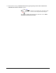
55. Do the fuses have continuity?
Replace fuse. See Parts Replacement section.
Then go back to Step 21.
Go to Step 56
56. Verify the DC Power Cable (P/N 193326) is securely connected between the Computer Interface
PWA Power Terminal and J2 labeled DC POWER IN on the Main Interface PWA.
57. Switch the Main Circuit Breaker to the
ON (I) position.
58. Locate the power LEDs on the Main Interface PWA.
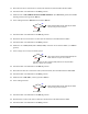
59. Are the green +5V, +12V, -12V, and A+5V LEDs illuminated?
Go to Step 60
Go to Step 21
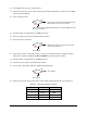
60. Measure VDC of DC Power Cable (P/N 193326) at J2 on Main Interface PWA (see Table 8-4).
Table 8-4 Cable P/N 193326 Connections
Pin Number Wire Color VDC
2Red
+5V
3 Orange
+12V
4White
-12V
5 Black ground
No
Yes
No
Yes
No
Yes