
Installation Manual


Troubleshooting 8-17
33. Disconnect the Servo Interconnect A Cable (P/N 06-4525-00) from the Main Interface PWA.
34. Switch the Main Circuit Breaker to the
ON (I) position.
35. Measure VDC at J29 (SERVO SIGNAL INTERCONNECT A) at Pin 36 and ground, then at Pin
33 and ground (connect ground to Pin 37).
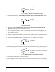
36. Is the reading ≥4 VDC at Pin 36 and ≥14 VDC at Pin 33?
Main Interface PWA (P/N 60-1200-00) has failed.
See Parts Replacement section.
Go to Step 37
37. Switch the Main Circuit Breaker to the OFF (0) position.
38. Reconnect the Servo Interconnect A Cable (P/N 06-4525-00) to the Main Interface PWA.
39. Switch the Main Circuit Breaker to the
ON (I) position.
40. Measure VAC at TP4 (A+5V) and at TP3 (A+15V) on the XY Servo Interface PWA. (Use TP5 for
ground).
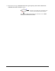
41. Is the Voltage correct at the Test Points (TPs)?
Servo Interconnect A Cable (P/N 06-4525-00) has
failed. See
Parts Replacement section.
The LED on the XY Servo Interface PWA (P/N 60-1211-00) has failed.
See
Parts Replacement section.
42. Switch the Main Circuit Breaker to the OFF (0) position.
43. Disconnect the XY Servo DC Power Cable (P/N 06-4530-00) from the Main Interface PWA J26.
44. Switch the Main Circuit Breaker to the
ON (I) position.
45. Measure VDC at J26, Pin 1 (connect ground to Pin 37).
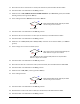
46. Is the reading ≥4 VDC?
Main Interface PWA (P/N 60-1200-00) has failed.
See
Parts Replacement section.
Go to Step 47
47. Switch the Main Circuit Breaker to the OFF (0) position.
48. Reconnect the XY Servo DC Power Cable (P/N 06-4530-00) to the Main Interface PWA.
49. Switch the Main Circuit Breaker to the ON (I) position.
No
Yes
No
Yes
No
Yes