
Installation Manual


8-16 Troubleshooting
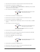
24. Are the green +5V, +12V, -12V, and A+5V LEDs illuminated?
Go to Step 53
Go to Step 25
25. Switch the Main Circuit Breaker to the OFF (0) position.
26. Visually inspect the Cables listed in Table 8-3 for damage and correct connections.
Table 8-3 Servo Cable Connections
Cable Part
Number
XY Servo Interface
Location
Main Interface
Location
06-4530-00 J18 J26
06-4525-00 J19 J29
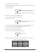
27. Are the Cables damaged or improperly connected?
Go to Step 33
If not properly connected, correct Cable connection and then go to Step 28.
If damaged, replace Cable(s) (P/N 06-4530-00, 06-4525-00). See
Parts
Replacement
section.
28. Switch the Main Circuit Breaker to the ON (I) position.
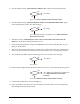
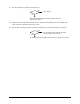
29. Locate the power LEDs on the XY Servo Interface PWA.
30. Are the green 5V, A+15V, and A+5V LEDs illuminated?
Go to Step 31
Stop here. Damaged or improperly connected cable is root cause of fault.
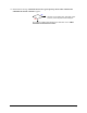
31. Are the green A+15V,and A+5V LEDs illuminated?
Go to Step 32
Go to Step 42
32. Switch the Main Circuit Breaker to the OFF (0) position.
No
Yes
No
Yes
No
Yes
No
Yes