
Installation Manual


Troubleshooting 8-15
12. Locate the Computer Passive Backplane located on the right inside wall of the Computer. Locate
four red LEDs labeled -5V, +5V, -12V, and +12V.
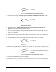
13. Are the LEDs illuminated?
Go to Step 14
Go to Step 18
14. Switch the Main Circuit Breaker to the OFF (0) position.
15. Disconnect the Computer Power Cable (P/N 193949) from Power Manager AC outlet AC1.
16. Verify that 208 to 240 VAC is at the AC1 outlet.
17. Switch the Main Circuit Breaker to the
ON (I) position.
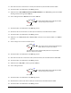
18. Does the outlet AC1 have 208 to 240 VAC?
Power Manager (P/N 62-1620-01) has failed.
See
Parts Replacement section.
Go to Step19
19. Check the continuity of the Computer Power Cable (P/N 193949).
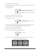
20. Does the Computer Power Cable have continuity?
Computer Power Cable (P/N 193949) has failed.
See
Parts Replacement section.
Computer (P/N 62-1632-00) has failed. See
Parts Replacement section.
21. Locate the power LEDs on the XY Servo Interface PWA.
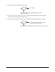
22. Are the green 5V, A+15V, and A+5V LEDs illuminated?
Go to Step 23
Stop here. No main power fault. Verify fault. If fault reoccurs, contact Asymtek
Technical Support.
23. Locate the power LEDs on the Main Interface PWA.
No
Yes
No
Yes
No
Yes
No
Yes