
Installation Manual


7-14 Theory of Operations
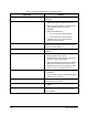
Description of Electrical and Pneumatic Paths
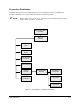
This subsection traces the electrical and pneumatic paths of commands for common actions of the
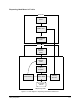
dispensing system. The explanation for each commanded action is illustrated first in a flow diagram
showing the major components involved, and then in a table identifying each component and its function
in executing the command. The following actions are discussed:
• Dispensing Head Moves in X- or Y-axis (see Figure 7-3, Table 7-3)
• Dispensing Head Moves in Z-axis (see Figure 7-4, Table 7-4)
• Dispensing Head Finds Home (see Figure 7-5, Table 7-5)
• Dispensing Head Performs a Height Sense (see Figure 7-6, Table 7-6)
• Conveyor Belt Moves (see Figure 7-7, Table 7-7)
• Stop Pins or Lift Tables/Clamp Bars Operate (see Figure 7-8, Table 7-8)
? NOTE Refer to the electrical and pneumatic diagrams in Appendixes A and B, if necessary.