
Installation Manual


Theory of Operation 7-13
Main Air Solenoid
Located behind the Low Pressure Sensor on the Servo Shelf, the Main Air Solenoid turns ON the air
pressure to the dispensing system when FmNT initializes and the green
ON (l) button on the Operator’s
Console is pressed.
Stop Pin Solenoid Valve
? NOTE Your dispensing system may have up to three of these valves depending on
system configuration.
The electrically controlled Stop Pin Solenoid Valves are located in the valve manifold at the rear of the
dispensing chamber. Air from these solenoid valves flows directly to the pneumatic solenoids for the Stop
Pins in the pre-dispense, dispense, and post-dispense stations on the Conveyor. Two hoses (one blue and
one black) run from each Stop Pin Solenoid Valve to its Stop Pin. Air pressure in the blue hose causes the
Stop Pin to block conveyance of the workpiece. Air pressure in the black hose causes the Stop Pin to
disengage, allowing the workpiece to be conveyed.
Clamp/Lifter Valve
? NOTE Your dispensing system may have up to three of these valves depending on
system configuration.
The Clamp/Lifter Valves (CLVs) are located in the valve manifold at the right rear of the dispensing
chamber. Each CLV provides air pressure for either a Clamp Bar or a Lift Table. For either device, air
leaves the CLV in two separate hoses, one blue and one black, which connect to the pneumatic cylinder
for that device.
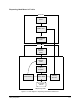
Each Lift Table has two Flow Control Valves (FCVs), one on each hose, between the CLV and the lift
cylinder (see Figure 7-8). Lift Table speed is controlled by restricting the flow of the cylinder exhaust.
Adjusting the flow in the black hose will affect upward speed of the Lift Table. Adjusting the airflow on
the blue line will affect the downward speed.
For Clamp Bars, the two hoses from the CLV bisect and go to the pneumatic cylinders attached to the
front and rear Conveyor Rails. Flow Control Valves are located on the pneumatic cylinders for each
Clamp Bar.