
Installation Manual


7-12 Theory of Operations
Fluid Air Pressure Regulators/Gauges
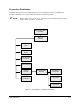
The two precision Fluid Air Pressure Regulators control the pressure to the fluid syringes. The pneumatic
pressure lines are routed from the Valve 1 or Valve 2 Fluid Pressure Regulators, under the Conveyor, and
to a cable conduit in the back of the dispensing system. The lines then go to the Servo Shelf and through
the Cat Track to the Control Valves on the back of Dispensing Head. From there, the pneumatic lines are
connected to quick-disconnect fittings located on the Dispensing Head bulkheads. Pressure readout for
each Regulator is on a configurable digital Pressure Gauge.
Valve Air Pressure Regulator/Gauge
The Valve Air Pressure Regulator controls pressure to the Valve Pressure Solenoid Valves on the back of
the Dispensing Head. The Solenoid Valves toggle the Dispensing Valves ON and OFF or can assist with
fluid refill, depending on the type of Dispensing Valve on your dispensing system. The two pneumatic
lines are routed the same way as the Fluid Air pressure lines above. The lines are blue for toggle-on air
(high bit) and black for toggle-off air (low bit). Pressure readout is on an analog Pressure Gauge.
Tooling Air Pressure Regulator/Gauge
The Tooling Air Pressure Regulator controls air pressure to Stop Pins and Lift Tables/Bar Clamps in the
dispensing chamber. Tooling pressure pneumatic lines are routed under the Conveyor base plate and up to
the Pneumatic Solenoid Valve Manifold located on top of the base plate at the rear of the dispensing
chamber. Pressure readout is on an analog Pressure Gauge.
Impingement Flowmeters
For systems with Impingement Heaters, the air is routed from a six-port junction on the Servo Shelf to a
Manual Shut-Off Valve located behind the Lower Front Cabinet Door. When the valve is opened, the air
pressure flows to the three Impingement Flowmeters (one for each Conveyor station) located just below
the Manual Shut-Off Valve. Regulated air from the Flowmeters is routed to the Impingement Heaters.
Dual-Action Solenoid
The Dual-Action Valve is located at the right rear of the Servo Shelf. Two pneumatic lines, one black and
one blue, go through the Cat Track to the Valve 2 Pneumatic Bulkhead. On the bulkhead, the blue hose
connects to the blue Toggle ON port and the black hose connects to the Toggle/OFF port. On systems
equipped with a Dual-Action Dispensing Head, the air pressure from these ports actuate/deactuate the
Toggle Cylinder that lowers/raises Valve 2.
Low Pressure Sensor
The Low Pressure Sensor is located on the right side of the Servo Shelf. It can be manually set for a
pressure from 10 to 100 psi (0.70 to 7.0 kg/cm2). The sensor will issue a signal when main air pressure is
lower than the manual set point. This signal will cause the yellow light on the Light Beacon to flash and
an FmNT error message to be displayed.