
Installation Manual


7-10 Theory of Operations
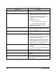
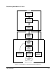
Power Distribution
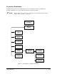
The distribution of power to dispensing system components is as specified in Table 7-2.
TIP Refer to the electrical diagrams in Appendixes A and B for further information.
Table 7-2 DC Power Supply Routing
Part Input
Power
Received
From
Output
Power
Power Destination
Power
Manager
208 to 240
VAC
Facility 240 VAC
24 VDC
ISO 24 VDC*
ISO 5 VDC*
• Computer Power Supply (240 VAC)
• Servo Supply (240 VAC)
• Conveyor/Heater Module Power (240
VAC)
• Main Interface PWA (ISO 24, ISO 5,
24 VDC)
Computer
250W
Power
Supply
208 to 240
VAC
Power
Manager
+5,-5,+12,
-12 VDC
• Main Interface PWA (12 VDC)
• Main CPU Board (5, +12, -12 VDC)
• PMAC Card (+12, -12 VDC)
• ITI Card, Other Cards (5, 12 VDC)
• PIO96 Card (5 VDC)
Main
Interface
PWA
24 VDC Power
Manager
+5,-5,+12,
-12 VDC
+5, -5, +12,
-12 VDC
PC Power
Supply
• XY Servo Interface (5, 24 VDC)
• Needle Sensor (24 VDC)
• Spare DC out (5, 24 VDC)
• Scale Power (12 VDC)
• Monitor (5, 12 VDC)
24 VDC Main
Interface
PWA
+5, -5, +12,
-12 VDC
Main
Interface
PWA
XY Servo
Interface
42 to 85
VDC
Servo Motor
Transformer
• X Y Servo Amplifiers (42-85 VDC)
• XY Linear Encoders (5 VDC)
• Pneumatic Solenoids (24 VDC)
• Fans (24 VDC)
• Beacon (24 VDC)
• Fluorescent Light (12 VDC)
• Z Servo Interface (5, 24 VDC)
• Dispense Head Controller (5, 24
VDC)
Conveyor
Controller
220 VAC Power
Manager
• Conveyor Motor
• Conveyor Sensor
• Heater Tooling / Needle Heater
Dispensing
Valve
24 VDC Dispense
Head
Controller
DV-7000 Series, DP-3000 Series,
DJ-2000 Series Dispensing Valves
* ISO = Isolated