
Installation Manual


xiv Table of Contents
TABLE OF TABLES
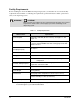
Table 1-1 Facility Requirements ......................................................................................... 1-2
Table 2-1 Calculation of Overturning Force, X-direction..................................................... 2-6
Table 2-2 Calculation of Overturning Force, Y-direction..................................................... 2-6
Table 2-3 Safety Warning Symbols .................................................................................. 2-10
Table 2-4 Beacon Color Indications ................................................................................. 2-22
Table 2-5 Recommended Decommission Procedures ..................................................... 2-23
Table 5-1 Light Beacon Test Matrix .................................................................................. 5-14
Table 5-2 SMEMA Communication Test Matrix................................................................ 5-29
Table 5-3 Heater Set Points ............................................................................................. 5-40
Table 6-1 Dispensing Calibration Module Components and Functions ............................ 6-11
Table 6-2 Heater Test Temperatures ............................................................................... 6-27
Table 7-1 Dispensing System Operational Sequence ........................................................ 7-3
Table 7-2 DC Power Supply Routing ................................................................................ 7-10
Table 7-3 Dispensing Head X-axis or Y-axis Movement .................................................. 7-16
Table 7-4 Dispensing Head Z-axis Movement.................................................................. 7-18
Table 7-5 Dispensing Head Finds Home .......................................................................... 7-20
Table 7-6 Performing a Height Sense .............................................................................. 7-23
Table 7-7 Conveyor Belt Movement ................................................................................. 7-26
Table 7-8 Stop Pin and Lift Table/Clamp Bar Operation .................................................. 7-27
Table 8-1 Major Troubleshooting Subsections ................................................................... 8-2
Table 8-2 Troubleshooting Summary – X and Y-axis Motion ............................................. 8-7
Table 8-3 Servo Cable Connections ................................................................................. 8-16
Table 8-4 Cable P/N 193326 Connections ....................................................................... 8-18
Table 8-5 Cable Connections to the Power Manager ....................................................... 8-22
Table 8-6 Cable P/N 06-4515-00 Connections ................................................................. 8-23
Table 8-7 Continuity Paths for Cable P/N 06-4515-00 ..................................................... 8-24
Table 8-8 Continuity Paths for Connector J5 .................................................................... 8-24
Table 8-9 Front EMO Cable Connections.........................................................................
8-
25
Table 8-10 Front EMO Pin Connections ............................................................................. 8-25
Table 8-11 Rear EMO Cable Connections ......................................................................... 8-26
Table 8-12 Rear EMO Button Cable Connections .............................................................. 8-27
Table 8-13 Rear EMO Button Pin Connections .................................................................. 8-27
Table 8-14 Vent Switch Faker Pin Connections ................................................................. 8-28
Table 8-15 Off Button Cable Connections .......................................................................... 8-28
Table 8-16 Cable P/N 06-4528-00 Pin Connections........................................................... 8-36
Table 8-17 Servo Amplifier Status ...................................................................................... 8-45