
Installation Manual


6-28 Calibration and Adjustment
7. When all loops have been configured, go to the On/Off column and double click on the
gray-shaded icon next to each loop.
> The icon will become yellow and red indicating that it is in the ON state.
8. Wait for the temperature in the present value (PV) column to reach steady-state temperature
at the set point (SP).
9. Measure and record the actual temperature of each Heater using a calibrated temperature
probe as follows:
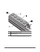
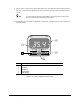
a. For Heater Tooling, take readings on the top surfaces at both ends and the middle of each
Heater. See Figure 6-13.
> The variance in temperature from left end of the Heater to the right end should
be ±5 °C.
b. For Needle Heaters, take readings on the internal wall of the Luer lock.
10. Subtract the measured temperature of the Heater from the present value (PV) temperature
displayed in the Heater Control Window. Record the resulting offset value.
11. In the Heater Control Window, double click on the channel (loop) name.
> The Loop Parameters dialog box for that specific Heater will open.
12. In the Loop Parameters dialog box, click on the
Input tab.
13. In the Input dialog box, enter the calculated offset value for the Heater in the Input Reading
Offset box.
14. Click on
OK.
15. Repeat Steps 11 through 14 for the other Heaters.
16. Click on
Exit to return to the Tools Window.