
Installation Manual


6-24 Calibration and Adjustment
Linear Encoder Gap Adjustment
It may be necessary to readjust the X and Y-axis Linear Encoder Scale-to-Scanner gap if the dispensing
system is moved or if you experience accuracy problems during dispensing.
CAUTION! The following procedure should only be performed by a trained
service technician.
Tools and Materials Needed
• Removable Thread Locker (P/N 40-0019) • 3-mm Hex Key
• 0.9-mm Encoder Gapping Tool (P/N 194983)
To check the X and Y-axis Linear Encoder gap:
1. Perform a Service Shutdown as specified in the Safety section of this manual.
2. Open the dispensing system Hatch.
WARNING! Make sure the yellow beacon light is displayed and all system motion has stopped
before reaching into the dispensing area. If the Heaters are hot, use extreme
caution when performing this operation.
3. Manually move the dispensing head to the front left side of the dispensing system.
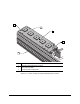
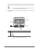
4. Locate the X-axis Encoder on top of the X-beam. See Figure 6-12.
5. Insert the 0.9-mm gapping tool between the X-axis Encoder Scale and its Scanner.
> The gapping tool should fit snugly into the space between the Scale and the Scanner. If it
does not, perform the Encoder adjustment procedure in this section.
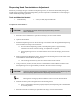
6. Manually move the dispensing head to the front right side of the dispensing system and
repeat Step 4.
7. Locate the Y-axis Encoder underneath the left side Y-rail. See Figure 6-12.
8. Manually move the X-beam to the front of the dispensing system.
9. Insert the gapping tool between the Y-axis Encoder Scale and its Scanner.
> The gapping tool should fit snugly into the space between the Scale and the Scanner. If it
does not, perform the Encoder adjustment procedure in this section.
10. Manually move the X-beam to the rear of the dispensing system and repeat Step 9.
11. Close the dispensing system Hatch.
12. Perform a Post-Service Start-up as specified in the Safety section of this manual.