
Installation Manual


Calibration and Adjustment 6-23
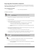
Impingement Heater Airflow Adjustment
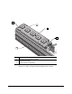
Adjustments to airflow Impingement Heaters at up to three processing stations (pre-dispense, dispense,
and post-dispense) is made on flowmeters located in the lower front cabinet. The Impingement Air
Shutoff Valve must be open to allow air to flow to the Impingement Air Flowmeters. When the Shutoff
Valve is open, airflow to an Impingement Heater is adjusted by turning the knob on its flowmeter. Flow
is read on the gauge directly above the flowmeter knob. See Figure 6-11.
Factors to be considered when determining the airflow include the following:
• Maximum airflow is 4.0 SCFM
• Size, weight, and securing of the workpiece (high airflow can cause
movement/misalignment)
• Effect of airflow on the time it takes to heat the workpiece to dispensing temperature
• Effect of airflow on how fast the heat tooling reaches/maintains steady-state temperature
• Ambient temperature of the dispensing area and its effects on dispensing fluid properties (pot
life, viscosity, cure time)
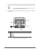
Item Description
1 Impingement Air Shutoff Valve
2 Flowrate Gauge
3 Flow Adjustment Knobs (Pre-heat, Dispense, Post-heat Station)
Figure 6-11 Impingement Flowmeter Location
3
1
2