
Installation Manual


Calibration and Adjustment 6-21
To adjust the Lift Table/Clamp Bar airflow:
1. Open the dispensing system Hatch.
WARNING! Do not reach into the dispensing chamber until yellow beacon light is displayed
and all system motion has stopped. If the Heaters are hot, use extreme caution
when performing this operation.
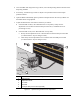
2. Locate the Flow Control Valves (FCVs) for the appropriate Lift Table or Clamp Bar.
See Figure 6-9 and Figure 6-10.
> To gain access to the FCVs, it may be necessary to remove the Dispensing Area Front
Cover as shown in Figure 6-4.
3. Adjust the FCVs as required.
> For Lift Tables, adjust FCV with the black hose for upward speed, and FCV with the
blue hose for downward speed.
> For Clamp Bars, use a flat bladed screwdriver to turn the recessed FCV adjustment
screws as necessary to synchronize the Clamps.
4. Repeat the operational check and adjustment procedures as necessary to obtain the
desired results.
5. Once you are satisfied with the operation of Clamp Bars or Lift Tables, click on
OK and then
in the next dialog box, click on
OK to return to the Main Window.
6. If it was removed, replace the Dispensing Area Front Cover and then close the dispensing
system Hatch.
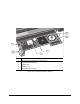
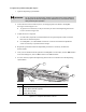
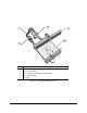
Item Description
1 Flow Control Valves (front rail)
2 Clamp Bar Pneumatic Cylinder
3 Front Conveyor Rail
4 Clamp Bar (rear rail)
Figure 6-9 Clamp Bar Pneumatic Controls
1
4
2
3