
Installation Manual


6-20 Calibration and Adjustment
Lift Table/Clamp Bar Airflow Adjustment
Flow Control Valves (FCVs) regulate the amount of air pressure supplied to the Lift Tables or Clamp
Bars to control the speed of its up and down movement. For optimum operation, the Lift Tables or Clamp
Bars should raise and lower at the same time and at the same rate.
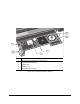
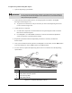
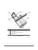
The location of the FCVs depends upon the device. The FCVs for Lift Tables are located on the
pneumatic hoses inside of the dispensing area, behind the Lift Tables. See Figure 6-10. The FCVs for
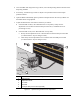
Clamp Bars are located on the Pneumatic Cylinders at each Conveyor station. One Clamp Bar is on the
front Conveyor Rail and one is on the rear Rail. See Figure 6-9.
? NOTE Air pressure to Stop Pins is constant and does not need to be adjusted.
CAUTION! The following procedures should only be performed by a trained
service technician.
Tools and Materials Needed
• Flat Head Screwdriver
• Phillips Head Screwdriver
To check the Lift Table/Clamp Bar operation:
1. In the FmNT Main Window, click on
Configuration and then select Setup Conveyors.
2. In the Setup Conveyors dialog box, click on the
Test I/O button. See Figure 5-10 in the
Power-up and Testing section of this manual.
3. In the MPC555 I/O Diagnostic dialog box, select the
Station I/O Diagnostic tab.
4. In the Station I/O Diagnostic dialog box, locate the
Clamp/Lifter output buttons.
5. Click the appropriate output button to turn the device ON and OFF. Monitor the Lift Table or
Clamp Bar to make sure it operates as follows:
> Lift tables should raise and lower at the same rate.
> Pairs of Clamp Bars should raise and lower simultaneously.
6. If a Lift Table or Clamp Bar does not operate properly, perform the pneumatic control
adjustment procedure in this section.