
Installation Manual


Calibration and Adjustment 6-19
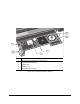
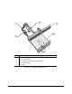
12. Slide the mode selection switch to Run.
> The Amplifier will display the incident light level.
13. Slide the switch to
Mode.
14. Dial the thumbwheel until the flashing cursor is next to Output 2 and then push down on the
thumbwheel.
15. Dial the thumbwheel until
L (light on) is displayed and then push down on the thumbwheel
to select.
16. Dial the thumbwheel until
non is displayed and then push down on the thumbwheel to select.
17. Dial the thumbwheel until
FR1 (Frequency 1) is displayed and then push down on the
thumbwheel to select.
18. To program Output 2, slide the mode selection switch to
Set.
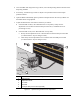
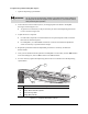
19. Load a sample workpiece onto the Conveyor and slide it over/under the optic sensor.
20. Push down on the thumbwheel to set the ON condition for Output 2.
> “2nd” will display after a moment.
21. Move the sample workpiece out from under/over the Board Sensor.
22. Push down on the thumbwheel to set the OFF condition for Output 2.
> GOOD should display for 2 seconds, indicating the ON-OFF threshold is identifiable. If
HARD is displayed, then the sensor may not be able to tell the difference between ON
and OFF. The Board Sensor lens will require realignment before proceeding.
23. While the programmed level for Output 2 is displayed, adjust the value up to 1000 by
toggling the mode selection switch until 1000 is displayed.
> This makes sure that Output 2 never turns ON.
24. Slide the mode selection switch to
Run.