
Installation Manual


Calibration and Adjustment 6-17
Downward-facing Board Sensors (X-1020 only)
Sensitivity adjustments for downward-facing Board Sensors are made on Fiber Optic Amplifiers
mounted under the Dispensing Area Front Cover. Depending upon system configuration, there may be as
many as three Board Sensors (pre-dispense, dispense, and post-dispense station).
CAUTION! The following procedure should only be performed by a trained
service technician.
Tools and Materials Needed
• Flat Head Screwdriver • Production Sample Workpiece
• Phillips Head Screwdriver
To adjust downward-facing sensor sensitivity:
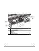
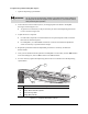
1. Remove the Phillips head screws securing the clear plastic Amplifier Cover to the
Dispensing Area Front Cover. See Figure 6-4.
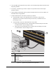
2. Locate the Fiber Optic Amplifier for the sensor you wish to adjust.
> The Amplifiers are in the order of the Conveyor stations. From back to front they are
pre-dispense, dispense, and post-dispense station Amplifiers.
3. Carefully remove the Amplifier Cover.
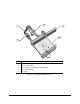
4. Slide the mode selection switch to
Mode. See Figure 6-8.
5. Dial the thumbwheel until the flashing cursor is next to
Output 1 and then push down on the
thumbwheel to select.
6. Dial the thumbwheel until
L (light on) is displayed and then push down on the thumbwheel
to select.
7. Dial the thumbwheel until
non (none) is displayed and then push down on the thumbwheel
to select.
8. Dial the thumbwheel until
FR1 (Frequency 1) is displayed and then push down on the
thumbwheel to select.
9. To program Output 1, slide the mode selection switch to
Set.
10. Make sure that no workpieces are under/over the sensor and then push down on the
thumbwheel to set the ON condition for Output 1.
> “2nd” will display after a moment.