
Installation Manual

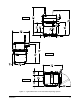

Table of Contents xi
TABLE OF FIGURES
Figure 1-1 Typical Dimensions for X-1000 Series Dispensing Systems .............................. 1-3
Figure 1-2 Axiom X-1000 Service Area Dimentions ............................................................ 1-4
Figure 2-1 Earthquake Protection, Side View ...................................................................... 2-5
Figure 2-2 Axiom X-1000 Center of Gravity ......................................................................... 2-7
Figure 2-3 Axiom X-1000 Weight Distribution ...................................................................... 2-8
Figure 2-4 Typical Warning Label Locations, Front View .................................................. 2-11
Figure 2-5 Warning Label Locations, Rear View ............................................................... 2-12
Figure 2-6 EMO Locations ................................................................................................. 2-13
Figure 2-7 Main Air Pressure Regulator and Gauge.......................................................... 2-15
Figure 2-8 Main Power Lock Out ....................................................................................... 2-18
Figure 2-9 Light Beacon .................................................................................................... 2-21
Figure 3-1 Removing the Shipping Brackets ....................................................................... 3-3
Figure 3-2 Placing the System ............................................................................................. 3-4
Figure 3-3 Typical dispensing chamber Packaging ............................................................. 3-6
Figure 3-4 Dispensing Head Stopper Locations .................................................................. 3-7
Figure 4-1 Monitor Installation ............................................................................................. 4-2
Figure 4-2 Removing the Servo Shelf Cover ....................................................................... 4-4
Figure 4-3 Light Beacon Installation .................................................................................... 4-5
Figure 5-1 Main Power Inlet ................................................................................................. 5-2
Figure 5-2 Main Air Inlet ...................................................................................................... 5-3
Figure 5-3 Cable Tensioner Locations ................................................................................. 5-4
Figure 5-4 Tensioning the Mechanical Cables .................................................................... 5-5
Figure 5-5 Gauge and Regulator Locations ....................................................................... 5-10
Figure 5-6 Power LED Location on the Main Interface Board ........................................... 5-12
Figure 5-7 Power LED Location on the XY Servo Interface Board .................................... 5-13
Figure 5-8 Dispenser I/O Test Dialog Box ......................................................................... 5-15
Figure 5-9 Conveyor Setup Dialog Boxes ......................................................................... 5-16
Figure 5-10 Height Sensor Setup Dialog Boxes .................................................................. 5-
17
Fi
gure 5-11 Dispenser Jog Commands Dialog Box ............................................................. 5-19
Figure 5-12 Machine Offsets Parameters Dialog Box .......................................................... 5-20
Figure 5-13 Dispensing Calibration Module ......................................................................... 5-21
Figure 5-14 Conveyor Jog Commands Dialog Box.............................................................. 5-24
Figure 5-15 Conveyor Rail Level Check .............................................................................. 5-27
Figure 5-16 TS-01 I/O Test Box Connections ...................................................................... 5-29