
Owner manual


3-28 Component Description
3.7.3.3 Major Probe Height and Probe-to-Needle Distance Adjustments
This procedure can be used to adjust both the height of the Height Sensor probe and the distance the
probe is from the dispensing needle.
To make major adjustments to the probe height:
1. Verify the following:
• The probe is in the down position
• The dispensing head is at the top of its Z-axis travel and at the front of the
dispensing chamber
• The dispensing needle has been installed
2. Press
OFF (0) on the operator’s console and open the hatch.
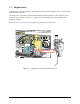
3. Insert a 0.050-inch hex key through the access hole in the right side of the Height Sensor as
shown in Figure 3-16.
NOTE It may be necessary to rotate the probe to align the setscrew with the access hole.
4. Slowly loosen the setscrew on the probe bushing just until you can move the probe.
CAUTION! Excess loosening of the probe setscrew may cause it to fall out of the bushing.
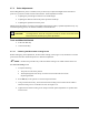
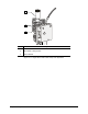
5. Adjust the probe so that the probe bend is aligned with the needle tip and that the probe tip is
within 1.0 mm (0.04 in.) from the dispensing needle as shown in Figure 3-15.
NOTE Aligning the probe bend with the needle tip automatically provides the recommended
1.78 to 2.54 mm (0.07 to 0.10 in.) height necessary for accurate height sensing.
6. While holding the probe in place, tighten the setscrew just until the probe is held firmly in
place and then remove the hex key. If the probe was rotated to allow access to the setscrew,
rotate the probe to its former position.
7. If necessary, make minor adjustments in the needle tip-to-probe bend alignment as discussed
earlier in this section.
8. If no further adjustments are necessary, close the hatch and press
ON (I) on the operator’s
console.
9. Perform a Valve Offsets routine as specified in the applicable Fluidmove User Guide (for
Windows NT or Windows XP) or Online Help.