
Owner manual


Component Description 3-13
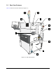
Table 3-6 Lower Rear Panel Features
Item Name Description
1 Main Air Gauge
Measures the regulated air pressure supplied to all other dispensing
system regulators.
2 Main Circuit Breaker
The main power switch for the dispensing system. It protects the
dispensing system from facility power surges and controls the flow of
facility AC power supplied to the power manager. A flange to the
right of the main circuit breaker allows it to be locked in the OFF
position during servicing. Switching OFF the main circuit breaker
cuts power to all dispensing system electrical components.
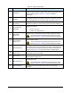
3 Rear Cabinet Door
Allows access to the electrical, pneumatic, and mechanical
components inside.
Only trained service technicians should open this door.
Refer to Section 2 – Safety for electrical safety information.
4 Main Power Cable
Connects the dispensing system power manager to the facility AC
power source.
5 Main Air Filter/Regulator
Controls the air pressure supplied to all other system regulators. The
regulator contains a built-in air filter and water trap to ensure that
only clean, dry air enters the system. Refer to 4.5.3 Pneumatic
Controls for the recommended pressure setting and other important
information.
6
Downstream Loader
Port
Allows the dispensing system to communicate with a downstream
loader for programming purposes only.
7 Upstream Unloader Port
Allows the dispensing system to communicate with an upstream
unloader for programming purposes only.
8 SECS/GEM Port
Allows the dispensing system to communicate with factory
management software running on the facility computer network .
9
SMEMA Connector
(upstream)
Allows for SMEMA communication between the dispensing system
and an upstream machine such as a loader.
10
SMEMA Connector
(downstream)
Allows for SMEMA communication between the dispensing system
and a downstream machine such as an unloader