
Owner manual


Component Description 3-9
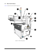
Table 3-4 Lower Front Cabinet Features
Item Name Description
1 View Port
Allows the operator to see the valve and fluid air pressure gauges
inside the cabinet.
2
Valve 1 Fluid Air
Regulator and Gauge
Controls/displays air pressure for the Valve 1 fluid syringe. The
regulator receives air from the main air regulator located on the back
panel of the dispensing system. Refer to 4.5.3 Pneumatic Controls
for recommended pressure settings and operating instructions.
3
Valve Air Regulator
and Gauge
(for dispensing valve)
Controls/displays the air pressure being supplied to the dispensing
valve. The type of dispensing valve installed on your system dictates
how this air is used. Refer to the applicable dispensing valve manual
for recommended pressure settings. Refer to 4.5.3 Pneumatic
Controls for recommended pressure settings and operating
instructions.
4
Valve 2 Fluid Air
Regulator and Gauge
Control/displays air pressure for the Valve 2 fluid syringe on systems
configured with the dual-action dispensing head option.
5
Cooler Air Regulator
and Digital Gauge
(X-1020 only)
The Controls/displays air pressure for the thermal control assembly
on a DJ-9000 Series dispensing valve. Refer to 4.5.3 Pneumatic
Controls for recommended pressure settings and operating
instructions.
6
Syringe Rack/
Documentation Holder
Holds spare fluid syringes and useful documentation.
7
Conveyor/Heater
Controller
Manages all conveyor-related functions including the width and belt
motors, sensors, pneumatic actuators, and the SMEMA interface
with upstream and downstream systems. The X-1020’s conveyor
controller also controls the heater tooling.
8 Computer
Runs the Fluidmove dispensing software. The computer-operator
interface includes:
• A 307-mm (12.1-in.), color LCD, flat panel monitor
• ASCII Keyboard
• Mouse
Refer to Section 7 – Specifications for detailed information.
9
Impingement
Flowmeters
(X-1020 only)
Controls the airflow through the impingement heaters in the
dispensing chamber. A manual shut-off valve controls the air going
to the flowmeters. Refer to 4.5.3 Pneumatic Controls for
recommended pressure settings and operating instructions.
10
Tooling Air Regulator
and Gauge
Controls the air pressure being supplied to the stop pins and lift
tables/clamp bars. The regulator receives air from the main air
regulator located in the back of the dispensing system. Refer to 4.5.3
Pneumatic Controls for recommended pressure settings and
operating instructions.