
Owner manual


Component Description 3-3
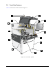
Table 3-1 Front View Features
Item Name Description
1 Light Beacon
A device that visually and audibly indicates dispensing system
operating status. It has red, yellow, green, and blue status indication
lights that can be solid or flashing. Refer to 2.8 Light Beacon for
additional information.
2 Work Light
A florescent light that illuminates the inside of the dispensing
chamber for maintenance or servicing operations whenever the
dispensing system is powered up. It is turned ON and OFF using a
power switch on the side of the light fixture.
3
Servo Shelf Cooling
Fan (intake)
Blows air through the servo shelf to cool the electronic components.
4 Conveyor
Allows parts to be conveyed by an o-ring belt from upstream
systems, to the dispensing station, and then to downstream systems.
All conveyors are SMEMA compatible and have adjustable rear rail
width. Refer to 3.2.2 Conveyor Features for additional information.
5 Conveyor Port
The entrance from upstream systems into the dispensing area and
the exit to downstream systems.
6 ON/OFF Buttons
The green ON (l) button illuminates and switches ON power to the
dispensing system mechanics.
The black OFF (0) button shuts down the dispensing activity and the
air pressure is vented, but computer and monitor power remains ON.
7 Grounding Strap Jacks
Grounding straps worn by the operator plug into these jacks to
prevent electrostatic discharge (ESD) damage to workpieces during
dispensing operations. Refer to Section 2 – Safety for additional
information.
8 Leveler (Foot Pad)
The footpads of the dispensing system. They are adjusted during
installation and should not need further adjustment unless the
system is moved to a new location.
9
Lower Front
Cabinet Door
Allows access to the system computer, conveyor/heater controller,
and pneumatic regulators and gauges. On the inside of the door,
there is space to store spare fluid syringes and documentation.
10 Keyboard/Mouse Tray Holds and protects the computer system keyboard and mouse.
11 Front EMO Button
A built-in safety feature located on both the front panel and back
panel of the dispensing system. Activating the EMO vents all
pressure in the pneumatic system, de-energizes the servo power
supply capacitors, and cuts power to all system components except
the computer and monitor. See Figure 3 5 for the location of the rear
EMO.
12 LCD Flat Panel Monitor
Provides the operator with Fluidmove software displays and a view
of the work area through the system camera.
13 Safety Interlock Switch
When the hatch is opened, the safety interlock immediately stops all
dispensing activity to protect the operator from injury. At the same
time, the light beacon displays a solid yellow warning light. Refer to
Section 2 – Safety for additional information.
14 Hatch
Allows the operator to view and, if necessary, access the dispensing
area. Opening the hatch activates the safety interlock feature.