
Quick Operations Owner's manual


3-10 Component Description
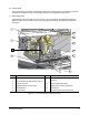
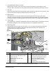
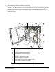
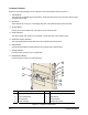
Rear View Features
Below are functional descriptions of X-1000 Series Dispensing System components shown in Figure 3-5.
Unless otherwise noted, Figure 3-5 and Figure 3-6 apply to both the X-1010 and X-1020 models.
1. Light Beacon
The Light Beacon is a device that visually and audibly indicates system operating status. It has red,
yellow, green, and blue status indication lights that can be solid or flashing. Refer to the Safety section
for additional information.
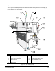
2. Side Air Vent
The Side Air Vent allows heat from Servo Shelf components to be exhausted to atmosphere to prevent
overheating. Airflow is provided by an intake fan on the opposite side of the Servo Shelf as shown in
Figure 3-1.
3. Cooling Fan (Dispensing Chamber)
The Cooling Fan exhausts heated air from the dispensing chamber to protect system components and
workpieces from overheating. The fan also exhausts any volatile organic compounds (VOC) that may be
present in the dispensing chamber.
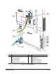
4. Main Power Inlet
The Main Power Inlet is where the Main Power Cable connects to the Power Manager.
5. Rear Cabinet Door
The Rear Cabinet Door allows access to the electrical, pneumatic, and mechanical components inside.
Because there are high-voltage components inside the cabinet, only trained service technicians should
open this door. Refer to the Safety section for additional safety information.
6. Main Air Inlet
The Main Air Inlet is where the facility air supply hose attaches to the dispensing system.
7. Electrical Cable Safety Cover
The Electrical Cable Safety Cover protects the electrical cables and pneumatic lines that run from the
lower cabinet to the Servo Shelf.
8. Emergency Off Button (EMO)
The EMO button is a built-in safety feature located on both the front panel and back panel of the
dispensing system. Activating the EMO vents all pressure in the pneumatic system, de-energizes the
servo power supply capacitors, and cuts power to all system components except the Computer and
Monitor. See Figure 3-1 for the location of the EMO button on the front of the dispensing system.
9. XY Servo Motor Safety Cover
The XY Servo Motor Safety Cover protects personnel from inadvertent contact with the high-voltage
X and Y Servo Motors. Because the Servo Motors are high-energy components, only trained service
technicians should remove this cover. Refer to the Safety section for electrical safety information.
10. Servo Shelf Safety Cover
The Servo Shelf Cover allows access to the electrical and pneumatic components inside. Because there
are high-voltage components on the Servo Shelf, only trained service technicians should remove this
cover. Refer to the Safety section for electrical safety information.