
Quick Operations Owner's manual


3-8 Component Description
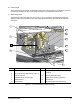
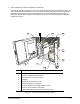
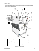
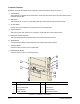
Lower Front Cabinet Features
Below are functional descriptions of X-1000 Series Dispensing System components shown in Figure 3-4.
1. Valve 1 Fluid Air Regulator and Digital Gauge
The Valve 1 Fluid Air Regulator and Gauge set controls air pressure for the Dispensing Valve 1 fluid
syringe on the Dispensing Head. There is also a Valve 2 Fluid Air Regulator and Gauge set that is used
for systems configured with the Dual-Action Dispensing Head option. Each Fluid Air Regulator receives
air from the Main Air Regulator located on the back panel of the dispensing system. Refer to “Pneumatic
Regulators and Gauges” in the Operation section for recommended pressure settings and operating
instructions.
2. Syringe Rack/Documentation Holder
Located inside the front cabinet door, this convenient feature can hold documentation and spare fluid
syringes needed by the operator.
3. Conveyor/Heater Controller
The Conveyor/Heater Controller manages all Conveyor-related functions including the width and belt
motors, Heater Tooling, sensors, pneumatic actuators, and the SMEMA interface with upstream and
downstream systems. The X-1010 has a Conveyor Controller that performs all of the same functions of
the Conveyor/Heater Controller except for the operation of the Heater Tooling. The X-1010 is not
equipped with Heaters.
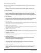
4. Computer
The Computer runs the FmNT dispensing software. The Computer-operator interface includes a 307-mm
(12.1-in.), color LCD, flat panel Monitor, and a Keyboard with Mouse as shown in Figure 3-1. Refer to
“Computer Features” later in this section for a detailed description of features.
5. Impingement Flowmeters
The Impingement Flowmeters control the airflow through the Impingement Heaters in the dispensing
chamber. A manual shut-off valve controls the air going to the flowmeters. Refer to “Pneumatic
Regulators and Gauges” in the Operation section for recommended pressure settings and operating
instructions.
6. Tooling Air Regulator and Gauge
The Tooling Air Regulator and Gauge control the air pressure being supplied to the Conveyor Stop Pins
and Lift Tables/Clamp Bars. The regulator receives air from the Main Air Regulator located in the back of
the dispensing system. Refer to “Pneumatic Regulators and Gauges” in the Operation section for
recommended pressure settings and operating instructions.
7. Cooler Air Regulator and Digital Gauge (standard on the X-1020)
The Cooler Air Regulator and Gauge set controls air pressure for the Thermal Control Assembly on a
DJ-9000 Series Dispensing Valve.
8. Valve 2 Fluid Air Regulator and Digital Gauge
The Valve 2 Fluid Air Regulator and Gauge set controls air pressure for the Dispensing Valve 2 fluid
syringe on the Dispensing Head. There is also a Valve 1 Fluid Air Regulator and Gauge set that is used
for systems configured with the Dual-Action Dispensing Head option.