
Quick Operations Owner's manual

Component Description 3-1
3 Component Description
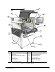
Front View Features
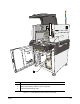
Below are functional descriptions of X-1000 Series Dispensing System components shown in Figure 3-1.
Unless otherwise noted, Figures 3-1 to 3-4 apply to both the X-1010 and X-1020 models
1. Light Beacon
The Light Beacon is a device that visually and audibly indicates dispensing system operating status. It
has red, yellow, green, and blue status indication lights that can be solid or flashing. Refer to the Safety
section for additional information.
2. Work Light
The Work Light is a florescent light that illuminates the inside of the dispensing chamber for maintenance
or servicing operations whenever the dispensing system is powered up. It is turned ON and OFF using a
power switch on the side of the light fixture.
3. Cooling Fan (Servo Shelf)
The DC-powered Cooling Fan blows air through the Servo Shelf to cool the electronic components.
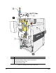
4. Conveyor
The Conveyor allows parts to be conveyed by an o-ring belt from upstream systems, to the dispensing
station, and then to downstream systems. All Conveyors are SMEMA compatible and have adjustable
rear rail width.
5. Conveyor Port
The Conveyor Port is the entrance from upstream systems into the dispensing area and the exit to
downstream systems.
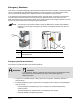
6. ON and OFF Buttons
The ON and OFF buttons are momentary push buttons located on the left side of the Operator’s
Console. When pressed, the green ON (l) button illuminates and switches ON power to the dispensing
system mechanics. When the OFF (0) button is pressed, the dispensing activity shuts down and the air
pressure is vented, but the Computer and Monitor power is not affected.
7. Grounding Strap Jack
The Grounding Strap Jack is located on the Operator’s Console. Grounding straps worn by the operator
plug into this jack to prevent electrostatic discharge (ESD) damage to workpieces during dispensing
operations. Refer to the Safety section for additional information.
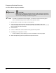
8. Levelers
The Levelers are the footpads of the dispensing system. They are adjusted during installation and should
not need attention unless the system is moved to a new location.
9. Lower Front Cabinet Door
The Lower Front Cabinet Door allows access to the system Computer, Conveyor/Heater Controller, and
pneumatic regulators and gauges. On the inside of the door, there is space to store spare fluid syringes
and documentation.