Axiom® Series X-1000 Series Dispensing System Quick Operations Manual P/N 7203768, Rev A
NOTICE This is an Asymtek publication, which is protected by copyright. Original copyright date 2005. No part of this document may be photocopied, reproduced, or translated to another language without the prior written consent of Asymtek. The information contained in this publication is subject to change without notice. Manuals on the Internet For the convenience of Asymtek customers and field service representatives, copies of this manual can be downloaded from: http://www.asymtek.com/support/manuals.
Table of Contents 1 Introduction ...................................................................................................................................... 1-1 Overview ............................................................................................................................................ 1-1 System Status.................................................................................................................................... 1-1 Safety First.......................
5 Maintenance ..................................................................................................................................... 5-1 Machine Status .................................................................................................................................. 5-1 Hazardous Materials .......................................................................................................................... 5-1 Scheduled Maintenance ........................................
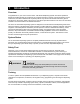
1 Introduction Overview Congratulations on your choice of the Axiom X-1000 Series Dispensing System! This Quick Operations Manual is intended primarily as a reference for production operators. However, process engineers, service technicians, and others unfamiliar with Asymtek products may also find this manual useful as a general introduction to the system. Refer to the Axiom X-1000 Series Operations Manual or the Axiom X-1000 Series Installation and Service Manual for detailed information.
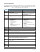
System Configuration Your dispensing system was configured at the Asymtek factory for your specific application prior to shipping. Table 1-1 compares the features and capabilities of the X-1000 Series Dispensing System models covered by this manual.
2 Safety This section is intended to provide basic safety information necessary for operating and servicing the Axiom X-1000 Series Dispensing System. To further optimize safe dispensing system operation, precautions and recommended practices are included with the procedures throughout this manual. WARNING! CAUTION! Unsafe equipment conditions can result in personal injury or property damage.
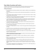
Basic Safety Precautions and Practices Compliance with the following recommended precautions and practices will prevent personal injury or damage to property during X-1000 Series Dispensing System operation and maintenance: Safety of Personnel • Only trained personnel should be permitted to perform operation, maintenance, and troubleshooting procedures. • There should always be a second person present when performing maintenance on a system under power.
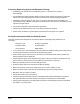
Preventing Dispensing System and Workpiece Damage • Immediately push the EMO button if dispensing system or a workpiece is in danger of being damaged. • Use standard Electrostatic Discharge (ESD) precautions when working near sensitive components. Always wear a grounding strap and connect it to the ESD ground before handling workpieces. • Immediately contain and clean up any caustic or conductive fluid spills as recommended in the material manufacturer’s MSDS.
Safety Warning Labels WARNING! CAUTION! Comply with all safety warning labels or serious injury to personnel or damage to the dispensing system will occur. Worn or damaged labels should be replaced with new labels having the same part number. Warning labels on your Axiom X-1000 Series Dispensing System point out areas where personnel must use extreme caution to prevent serious injury and property damage.
3 1 2 Item Description 1 Electrical Hazard Warning Label 2 Heavy Object Warning Label (on side of Computer) 3 Thermal Hazard Warning Label Figure 2-1 Typical Warning Label Locations, Front View Safety 2-5
1 4 2 3 1 Item Description 1 Electrical Hazard Warning Label 2 Heavy Object Warning Label (on side of Transformer) 3 Thermal Hazard Warning Label 4 Fire Hazard Warning Label Figure 2-2 Warning Label Locations, Rear View 2-6 Safety
Emergency Shutdown Your Axiom X-1000 Series Dispensing System features EMO buttons that the operator or service technician can use to immediately stop all dispensing operations in case of emergency. This feature helps prevent injury to personnel and damage to the dispensing system and workpieces being processed. Your dispensing system design includes two EMO buttons. One EMO button is located on the Operator’s Console, and the second is located on the rear panel of the dispensing system (see Figure 2-3).
Emergency Shutdown Recovery To recover after an emergency shutdown: WARNING! CAUTION! Do not restart the dispensing operation until the condition causing the emergency shutdown has been alleviated. Failure to comply could cause serious injury to the user and serious damage to the dispensing system. " NOTE 1. Open the Hatch and clear the Conveyor of all workpieces. 2. Locate and remedy the cause of the emergency shutdown.
Safety Interlock System The Safety Interlock System is a built-in safety feature that automatically reduces dispensing system servo power when the Hatch is opened. This system mainly prevents personnel from being injured by movement of the Dispensing Head and Conveyor. This system consists of the following: • A key attached to the dispensing system Hatch that fits into a switch that is attached to the right side doorframe. • A Light Beacon. • The system Computer and FmNT software.
Light Beacon The Light Beacon is a device that displays system status and can warn the Operator when fault conditions exist. The Beacon has red, yellow, green, and blue lights that can be solid or flashing. The Beacon also has an audible alarm. Table 2-2 provides possible reasons for each color indication. Software and hardware share control of the Beacon lights. Sometimes, hardware-driven displays override those caused by software conditions and sometimes software-driven displays override.
3 Component Description Front View Features Below are functional descriptions of X-1000 Series Dispensing System components shown in Figure 3-1. Unless otherwise noted, Figures 3-1 to 3-4 apply to both the X-1010 and X-1020 models 1. Light Beacon The Light Beacon is a device that visually and audibly indicates dispensing system operating status. It has red, yellow, green, and blue status indication lights that can be solid or flashing. Refer to the Safety section for additional information. 2.
10. Keyboard/Mouse Tray The Keyboard and Mouse Tray holds and protects the Computer System keyboard and mouse. 11. Emergency Off (EMO) Button The EMO button is a built-in safety feature located on both the front panel and back panel of the dispensing system. Activating the EMO vents all pressure in the pneumatic system, de-energizes the servo power supply capacitors, and cuts power to all system components except the Computer and Monitor. See Figure 3-5 for the location of the rear EMO. 12.
14 1 2 12 13 3 4 11 10 5 9 6 8 7 Item Description Item Description 1 Light Beacon 8 Leveler (Foot Pad) 2 Work Light 9 Lower Front Cabinet Door 3 Servo Shelf Cooling Fan (intake) 10 Keyboard/Mouse Tray 4 Conveyor 11 Front EMO Button 5 Conveyor Port 12 LCD Flat Panel Monitor 6 ON/OFF Buttons 13 Safety Interlock Switch 7 Grounding Strap Jacks 14 Hatch Figure 3-1 Front View (Typical) Component Description 3-3
X-1010 Dispensing Chamber Features Below are functional descriptions of X-1000 Series Dispensing System components shown in Figure 3-2. 1. Dispensing Head The Dispensing Head is mounted on the X-beam and is moved by a positioning system in the X, Y, and Z-axes. It carries the Dispensing Valve to a precise position over the workpiece in the dispense station of the Conveyor. The Camera and Height Sensor (option) are also mounted on the Dispensing Head. 2.
10. Fluid Syringe The Fluid Syringe is mounted on the Dispensing Valve and contains the fluid to be dispensed. The fluid manufacturer packages the fluid in the syringe according to your application requirements. 11. Dispensing Valve The Dispensing Valve also referred to as a “pump” or “jet” is mounted on the Dispensing Head and dispenses fluid onto the workpiece. Refer to the appropriate Dispensing Valve manual for additional information.
X-1020 Dispensing Chamber Features Below are functional descriptions of X-1000 Series Dispensing System components shown in Figure 3-3. 1. Dispensing Head` The Dispensing Head is mounted on the X-beam and is moved by a positioning system in the X, Y, and Z-axes. It carries the Dispensing Valve to a precise position over the workpiece in the dispense station of the Conveyor. The Camera and Height Sensor (option) are also mounted on the Dispensing Head. 2.
8. Look Down Board Sensors (X-1020) Board Sensors mounted on top of the Conveyor rail detect the presence of the workpiece at each Conveyor station. There may be as many as three Board Sensors mounted along the length of the rail. 9. Stop Pins Stop Pins are pneumatic devices that physically stop the workpiece at a specific Conveyor station. There may be as many as three Stop Pins attached to the rear Conveyor rail. 10.
Lower Front Cabinet Features Below are functional descriptions of X-1000 Series Dispensing System components shown in Figure 3-4. 1. Valve 1 Fluid Air Regulator and Digital Gauge The Valve 1 Fluid Air Regulator and Gauge set controls air pressure for the Dispensing Valve 1 fluid syringe on the Dispensing Head. There is also a Valve 2 Fluid Air Regulator and Gauge set that is used for systems configured with the Dual-Action Dispensing Head option.
9. Valve (Dispensing Valve) Air Regulator and Gauge The Valve Air Regulator and Gauge control the air pressure being supplied to the Dispensing Valve. The type of Dispensing Valve installed on your system dictates how this air is used. Refer to the applicable Dispensing Valve Installation and Operations Manual for recommended pressure settings. Refer to “Pneumatic Regulators and Gauges” in the Operation section for recommended pressure settings and operating instructions.
Rear View Features Below are functional descriptions of X-1000 Series Dispensing System components shown in Figure 3-5. Unless otherwise noted, Figure 3-5 and Figure 3-6 apply to both the X-1010 and X-1020 models. 1. Light Beacon The Light Beacon is a device that visually and audibly indicates system operating status. It has red, yellow, green, and blue status indication lights that can be solid or flashing. Refer to the Safety section for additional information. 2.
11. Top Air Vents The two Top Air Vents allow heat from the Dispensing Chamber to be exhausted to atmosphere. On X-1010 systems, air flows passively out of the Chamber. On X-1020 systems, exhaust fans rapidly remove heated air from the Chamber.
Rear View Features Close-up Below are functional descriptions of X-1000 Series Dispensing System components shown in Figure 3-6. 1. Main Air Gauge The Main Air Gauge measures the regulated air pressure supplied to all other dispensing system regulators. 2. Main Circuit Breaker The Main Circuit Breaker is the main power switch for the dispensing system. It protects the dispensing system from facility power surges and controls the flow of facility AC power supplied to the Power Manager.
10 1 2 3 9 8 7 6 5 4 Item Description Item Description 1 Main Air Gauge 6 SMEMA Connector (upstream) 2 Main Circuit Breaker 7 SECS/GEM Port 3 Rear Cabinet Door 8 Downstream Loader Port 4 Main Power Cable 9 Upstream Unloader Port 5 SMEMA Connector (downstream) 10 Main Air Filter/Regulator Figure 3-6 Rear View Close-up Component Description 3-13
Computer Features Below are functional descriptions of the Computer Control Panel features shown in Figure 3-7. 1. CD-RW Drive The Computer is equipped with a CD-RW Drive. Press the button below and to the right to load or eject a writeable compact disk. 2. Disk Drive The Computer has a 3.5-inch, 1.4-MB floppy disk drive. Insert disks through the drive door flap. 3. On-Off Switch Press (l) to turn the Computer ON. Press (0) to turn the Computer OFF. 4.
4 Operation System Startup/Shutdown This subsection details basic start-up and shutdown procedures based on different levels of operation. These procedures are offered as general recommendations and suggestions when starting and/or shutting down your Axiom X-1000 Series Dispensing System. Your actual start-up and shutdown procedures may vary. Startup If necessary, refer to the figures in the Component Description section to identify system components. To power on the dispensing system: 1.
4. If a message to run a Valve Offsets routine appears, click on OK. ! 5. When the FMNT Message 30416 - Dispenser Motor References Not Found (Figure 4-1) appears, click OK to Home the Dispenser. ! 6. " A message should appear that indicates the dispensing system is being initialized. The FmNT Main Window (Figure 4-2) will open. Check to make sure the Dispensing Head is in the proper Home position. NOTE To start a production run, see “Running Production” later in this section.
Shutdown Emergency Shutdown WARNING! CAUTION! In an emergency, failure to completely shut down power to the dispensing system with the EMO can cause serious injury to the user and damage to the dispensing system. During an emergency or malfunction, press the EMO button – the large red button on the Control Panel or on the back of the dispensing system (see Figure 2-3 in the Safety section for locations).
Service Shutdown We recommend that you incorporate the following steps into your service shutdown routine: 1. Perform a Production Shutdown as described in the previous subsection. 2. Turn OFF (0) the Main Power Circuit Breaker at the rear of the system. Lock out and tag out the power as specified in the Safety section of the Axiom X-1000 Series Operations Manual or the Axiom X-1000 Series Installation and Service Manual. 3. Verify pressure at the Main Air Inlet is 0 psi. 4.
1 2 3 Item Description 1 Y-axis Controls (rear rail forward and backward movement) 2 X-axis Controls (belt left and right movement) 3 Conveyor Radio Button Figure 4-3 Conveyor Position Controls 3. Conveyor position controls (Figure 4-3) operate as follows: ! On the X-Y control panel, the arrows pointing to the Left move the Conveyor belt to the left and the arrows pointing to the Right move it to the right.
4. Dispensing Head position controls (Figure 4-4) operate as follows: ! On the X-Y control panel, the arrows pointing to the Left move the Dispensing Head to the left and the arrows pointing to the Right move it to the right. ! On the X-Y control panel, the arrows pointing Up move the Dispensing Head toward the back of the dispensing area and the arrows pointing Down move it toward the front of the dispensing area.
Table 4-2 Dispensing Head Position Controls: Jog Distance and Velocity(1) Movement Axis Distance mm (inch)(2) Velocity mm/sec (in/sec) Distance mm (inch)(2) Velocity mm/sec (in/sec) X-Y 0.0254 (0.001) 1.27 (0.050) 2.54 (0.100) 88.9 (3.50) Z 0.0254 (0.001) 2.54 (0.100) 1.27 (0.050) 10.16 (0.40) Notes: (1) Default distances and velocities. Refer to the FmNT User Guide or FmNT Online Help to modify jog distances and velocities. Distance per Mouse click on the arrow button.
Control Buttons and Switches The location of the primary control buttons and switches that are accessible to the operator are located as shown in Figure 4-5. The function of these buttons and switches is described in Table 4-4. Table 4-4 Control Buttons and Switches Button/Switch Appearance Function The large, red EMO button is located on the right side of the Operator’s Console and on the rear right side of the dispensing system.
2 1 3 4 Item Description 1 System ON and OFF Buttons 2 Front EMO Button 3 Rear EMO Button 4 Main Power Circuit Breaker Figure 4-5 Operator Accessible Switches and Buttons Operation 4-9
Pneumatic Regulators and Gauges The Axiom X-1000 Dispensing System has Pneumatic Regulators and Gauges that control the air for the following systems: • Main Air • Fluid • Dispensing Valve [Operation and Cooling (DJ-9000)] • Tooling (if applicable) • Impingement Heaters (if applicable) The Main Air Pressure Regulator and Gauge set is located on the back panel at the right rear of the dispensing system as shown in Figure 4-6.
To adjust the Main Air Pressure Regulator: 1. Verify that the facility air supply is connected to the Main Air Inlet. 2. At the top of the Filter-Regulator, locate the Regulator adjustment knob. See Figure 4-6. 3. Gently pull up on the adjustment knob to unlock it. 4. While watching the gauge, rotate the adjustment knob: ! Clockwise to increase pressure up to the desired level. ! Counterclockwise to decrease pressure. " 5.
Fluid Air Pressure Regulator and Gauge The Fluid Air Pressure Regulator and Gauge set (Figure 4-7) consists of a precision Regulator and a digital gauge. This set precisely controls the air pressure going to the receiver head of the fluid syringe or reservoir. The system maintains a steady flow of dispensing fluid to the Dispensing Valve by applying air at a constant pressure to the syringe or reservoir while the dispensing system is operating.
1 11 2 10 9 3 4 2 5 X-1020 6 7 8 1 12 2 9 3 4 X-1010 2 Item Description 8 Item Description 1 Fluid Air Pressure Regulators 7 Cooler Air Pressure Regulator 2 Fluid Air Pressure Digital Gauge 8 Tooling Air Pressure Regulator 3 Valve Air Pressure Gauge 9 Tooling Air Pressure Gauge 4 Valve Air Pressure Regulator 10 Cooler Air Pressure Digital Gauge 5 Tooling Vacuum Gauges (optional) 11 Impingement Air Shutoff Valve 6 Impingement Flowmeters 12 Lift Table Air Shutoff V
To adjust Valve and Tooling Air Pressure Regulators: 1. Verify that the dispensing system is ON. ! The Light Beacon will display a green or solid yellow light. 2. Open the lower front cabinet door and find the appropriate pressure Regulator. See Figure 4-7. 3. Gently pull the Regulator adjustment knob downward to unlock. 4. While watching the appropriate gauge, rotate the adjustment knob: ! Clockwise (right) to increase pressure. ! Counterclockwise (left) to decrease pressure. " 5.
Dispensing Head Accessories Pneumatic and Electrical Connections Pneumatic Fittings The pneumatic fittings and hoses supplying pneumatic pressure to components on the Dispensing Head are color coded for easy identification. Table 4-6 provides fitting and hose colors with a description of their use.
1 3 4 2 4-8a Valve 1 Bulkhead 10 5 9 6 4-8b Valve 2 Bulkhead 7 Item 8 Description 1 Valve 1 Fluid Air Fitting (Silver) 2 Valve 1 OFF Fitting (Black) 3 Valve 1 ON Fitting (Blue) 4 Valve 1 Cooler Air (Green) 5 Toggle Cylinder ON (Blue) 6 Valve 2 ON (Blue) 7 Valve 2 OFF (Black) 8 Valve 2 Fluid Air Fitting (Silver) 9 Valve 2 Cooler Air (Green) 10 Toggle Cylinder OFF (Black) Figure 4-8 Pneumatic Bulkheads Close-up 4-16 Operation
Running Production The following procedure assumes that the Computer and Monitor are on and FmNT has been started as described in “Starting Fluidmove for Windows (FmNT)” previously in this section. To start a production run: 1. Verify that the Main Air, Valve, and Fluid pressures are set to the desired level. ! If not, adjust pressure as described under “Pneumatic Regulators and Gauges” earlier in this section. 2. Verify that all Dispensing Head accessories are properly connected.
9. In the Production Window, click on Run and then click on the Run Production button. ! 10. This brings up the Run Window. Click on Go to activate the dispensing process. See Figure 4-11 CAUTION! If the message “Clear conveyor before continuing” appears on the Monitor screen, remove any workpieces from the Conveyor before clicking on OK. Dots.fmw VVS.fmw Lines.fmw WCLine.fmw Multipas.fmw Program1.fmw SR_Rectangle.fmw Underfill.
5 Maintenance This section contains the recommended scheduled, routine, and preventive maintenance procedures for your Axiom X-1000 Series Dispensing System. Performing the recommended maintenance procedures at the intervals suggested in this section will increase system life and ensure high quality dispensing performance for every production run. Machine Status Unless otherwise specified, the dispensing system may be left powered ON while performing the following maintenance procedures.
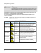
Scheduled Maintenance Following a routine maintenance schedule can prevent part degradation and ensure high quality performance for every production run. There are several simple procedures you can perform on a regular basis to ensure quality dispensing and optimize system performance. The maintenance schedule for the X-1000 Series Dispensing System is predicated on normal operation. The maintenance task, interval, and instructions are summarized in Table 5-1.
Table 5-1 Recommended Maintenance (continued) Maintenance Task Inspect Height Sensor Probe. Recommended Frequency Daily Instructions Visually inspect the probe for fluid buildup and damage. • Clean fluid on the probe using a soft cloth with cleaning agent recommended by the fluid manufacturer (see the MSDS). • Drain Water Trap. Clean Hatch window and Monitor screen. Weekly or When Full Weekly To replace damaged probes, refer to “Replacing a Height Sensor Probe” in this section.
Replacing Consumables Consumables are items that are discarded and replaced on a regular basis. The following items are common consumables and should be replaced at the intervals recommended in Table 5-1: • Purge Boots • Weigh Station Cup • Purge Cup • Banjo Wiper Tools and Materials Needed • Needle-nosed Pliers • Replacement Purge Boot (see Table 5-2) • Isopropyl Alcohol • Replacement 1 oz.
9. 10. Reinstall the cover onto the Purge Station. Close the Hatch. ! If a dispensing program was running, it will restart where it left off.
To replace the Purge and Weigh Station cups: WARNING! " NOTE The Valve Offsets routine does not need to be performed after replacing the Purge Station and Weigh Station cups. 1. When the dispensing system is idle, open the dispensing system Hatch. 2. Remove the Purge and Weigh Station covers. See Figure 5-2. 3. Remove and discard the plastic cup inside the Purge Station and inspect the interior surfaces for spilled fluid. ! 4.
4 1 5 2 3 Item Description 1 Weigh Station Cover (P/N 194543) 2 Banjo Wiper (P/N 02-1570-03) 3 Weigh Station Cup (P/N 58-0030) 4 Purge Station Cover (P/N 194701) 5 Purge Station Cup (P/N 58-0030) Figure 5-2 Replacing Purge and Weigh Station Cups Maintenance 5-7
Draining the Water Trap The facility air supply may contain moisture that can damage the dispensing system. The Water Trap condenses this moisture before it enters the dispenser pneumatic system. The operator or technician should drain the Water Trap weekly or whenever it is full. WARNING! Do not remove the bowl guard protecting the Water Trap.
1 2 4 3 OPEN Item CLOSE Description 1 Regulator 2 Main Air Inlet 3 Drain Knob 4 Water Trap Bowl Guard (bowl inside) Figure 5-3 Draining the Water Trap Maintenance 5-9
Replacing a Height Sensor Probe " NOTE Each valve used on the X-1000 Series Dispensing System has a specific Height Sensor probe. If you change from one Dispensing Valve to another, you may also need to change the Height Sensor probe. Contact Asymtek for additional information. Tools and Materials Needed • 0.
9. Perform a Valve Offsets routine. Refer to the FmNT User Guide or Online Help. 4 1 2 3 Item Description Item Description 1 Probe Bushing 3 Probe Block 2 Height Sensor Probe 4 Probe Setscrew Access Hole Figure 5-4 Height Sensor Probe Installation 1 2 1.78 – 2.54 mm (0.07 – 0.10 in.) 3 1.0 mm (0.04 in.
Asymtek Headquarters 2762 Loker Avenue West Carlsbad, CA 92008-6603 USA Tel: (760) 431-1919 1-800-ASYMTEK (1-800-279-6835) P/N 7203768, Revision A © 2005